Post #9: "How to adapt a [insert device type here] to 240V mains?" or the like. Reading is an art and on a technical forum one would not expect "amp". If you want a fast and adequate advice for your issue you are the one that needs to give enough information!!!
So you are talking to the manufacturer but in the meantime ask for help here?!? You don't mention the brand and typenumber so everything is single direction to "me/myself/I". OK. In the past years I have learned that this forum flourishes because of sharing information. Give and take, old fashioned stuff really. Recent experiences show me that the balance is a little skewed. There are ones that just take and ones that give. The pattern is often similar. Very scarce information (again; car for sale. color: red) given by the requester forcing the members to ask for details which are then still given reluctantly (the requesters time is valuable you know). I would not mind if a point system would be introduced so members can be awarded points.
Also it would be quite good that the "request for help" threads would have to comply to a minimum standard of information given. Like brand, type, schematics, pictures ....This would be done in form template mode. No information filled in? Then no thread 🙂
Last edited:
"I will not put the device name as yet until I finish talking to the manufacturer to try and get their help."
Why do you have a problem with being up front with the manufacturers name and model?
Why do you have a problem with being up front with the manufacturers name and model?
Seriously, not sure why/how
and it´s STILL obscure:
Oh well.

JMFahey, the title was changed to what the OP requested it to be changed to. Moderation do not apply discretion to the merit of the title, unless the title contravenes a forum rule, or is in some way prejudicial to the interest of the thread.
Dear sangram, no complaints about your job, at all, quite the contrary.🙂
Yes, call me being VERY intrigued about why a clarification request showed NO useful data and of course I had to ask. 😕
Even after jean-paul clearly specified it with all the letters, so it could not lead to any confusion:
Take care Friend.
Yes, call me being VERY intrigued about why a clarification request showed NO useful data and of course I had to ask. 😕
Even after jean-paul clearly specified it with all the letters, so it could not lead to any confusion:
"How to adapt a [insert device type here] to 240V mains?" or the like.
Take care Friend.
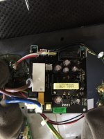
At least now we have door and engine cover closeups. taken from 10cm away, and we can confirm the car is GREEN, dark green in fact.
And you think we are not going forward? 😛
Seriously, not sure why/how
and it´s STILL obscure:
Oh well.
Whats this supposed to mean?
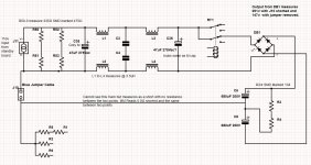
With my limited skills I managed to trace the circuit as per attached pic.
This is a dead-standard dual voltage 115V/230V rectifier. Remove the jumper for 230V lands. (Chokes and high-number caps are frills to reduce interference, not needed for basic operation/understanding.)
But what is this "110V standby board"? Is there more not shown?
Attachments
Last edited:
In this case, you do not need an AC divider.I have removed the jumper and the amp works plugged into 240v
Here it is anyway: Here is an elegant (insane?) way of converting 220V to 110V
I do not recommend using it: it is a fun, proof-of-concept design but in real applications, especially for a SMPS having a direct input capacitive filter, the peak currents would be problematic
No a proof-of-concept design with issues should definitely not be recommended to the average DIYer. Please note that the wire jumper is too much for many.
Stuff that is sold globally is easily adaptable in most cases. If not one better had bought the correct mains voltage gear.
Stuff that is sold globally is easily adaptable in most cases. If not one better had bought the correct mains voltage gear.
Last edited:
- Home
- Amplifiers
- Power Supplies
- How to adapt a REL S510 from 120V to 240V mains