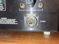
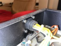
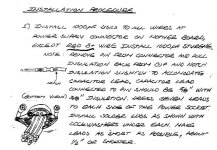
I am trying to follow the (attached) instructions to add RFI filter capacitors to the power leads connecting the power supply and preamp modules of my Audio Research SP10. The problem is, I cannot figure out how to remove pins from the connector! The illustration provided shows little "fins" that could be depressed by a pin tool, but I don't see any evidence of these fins in the pictures.
Attachments
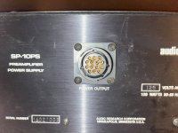
If you look at the picture with the male pins, it looks like they flare out at the base. Would I need a pin tool that could fit over that flared part?
I do not think you cannot get the pins out without damaging them. You would need pins that fit that connector. Look for a diagram of the pins and you should see a retaining flap that compresses when sipped in and will expands when the pin is pushed far enough in.
The instructions I linked seem to imply that they come out. I just cant identify the retaining flap.
There are pin extractor tools designed for that, otherwise it's impossible.
There are many kinds and sizes, but it has to be exactly the right size for the particular connector.
The mfr part number should be somewhere on the connector, possibly it's an Amphenol circular connector.
If you damage the pin, you will need a much more expensive mfr spec ratcheting crimp tool to install another pin.
An example, but this may not be the right one. You need the mfr connector part number to find the proper extractor.
https://www.amazon.com/JRready-Extractor-Removal-Connectors-Connector/dp/B0B6FMZMH4/ref=sr_1_5
Last edited:

Thank you, I figured I would need a tool similar to what @rayma linked. I was hoping it would be somewhat generic to the diameter of the pin, or that these sorts of connectors were following some sort of common standard. I can contact Audio Research and see if they can help…
In the mean time, is it possible to cut a notch in the insulation to “tap” the wire and connect the drain capacitors? Or would that be “bad form”?
In the mean time, is it possible to cut a notch in the insulation to “tap” the wire and connect the drain capacitors? Or would that be “bad form”?
There's no such thing as a "common standard" where connectors are concerned. Every manufacturer has has their own unique style, usually on purpose. 🙂or that these sorts of connectors were following some sort of common standard.
jeff
I went on Mouser, browsed to “circular connectors”, then selected “DIN connectors”, then selected number of pins, and found many connectors similar to what’s on my unit, like this: https://www.mouser.com/ProductDetail/Amphenol-Tuchel/C091-31G014-200-5-U
That would seem to indicate that, at least what I found, is somewhat “standard”, since there is a category for “14 pin DIN connectors”. Shouldn’t I be able to buy a tool for “DIN connectors”, or something similar?
That would seem to indicate that, at least what I found, is somewhat “standard”, since there is a category for “14 pin DIN connectors”. Shouldn’t I be able to buy a tool for “DIN connectors”, or something similar?
It would depend on the manufacturer of the connector in question. If they offer a "tool" then I guess the answer is yes.Shouldn’t I be able to buy a tool for “DIN connectors”, or something similar?
If the pins are soldered to each wire, that could present a problem.
jeff
I’m assuming this is possible because the guide I have says it possible.
Does the DIN standard define some commonality that would be true across manufacturers?
Does the DIN standard define some commonality that would be true across manufacturers?
Well it's pretty vague. I would proceed with caution. If you can identify who made the connector, that might help.I’m assuming this is possible because the guide I have says it possible.
No idea.Does the DIN standard define some commonality that would be true across manufacturers?
jeff
That looks pretty plausible. How’d you find it?
Am I onto something thinking that DIN defines standards across parts?
Am I onto something thinking that DIN defines standards across parts?
I have to wonder if clamp on ferrite cores could be another option for this problem.
Are you having problems with RF leaking into this device?
Might be another cure with less pain.
Are you having problems with RF leaking into this device?
Might be another cure with less pain.
Yes, I am getting clear radio signal as well as static/noise. It has been a problem with other devices.
Ferrite makes sense. When I saw that there was an actual, documented RFI mod for this preamp though, I thought I would start there.
Ferrite makes sense. When I saw that there was an actual, documented RFI mod for this preamp though, I thought I would start there.
Any chance your house is not grounded well? I bought a house years ago and fought with RF problems. Added an addition and while replacing the panel and meter and pole also realized that there was no ground at the panel and what ground clamped to the cold water lines really did not connect to anything.
Also a ground line at the closest pole had been harvested at some point.
Anyway all of my RF problems seemed to go away with sufficient grounding.
Also a ground line at the closest pole had been harvested at some point.
Anyway all of my RF problems seemed to go away with sufficient grounding.
- Home
- Design & Build
- Construction Tips
- How the heck to I remove pins from this 14-pin power connector?