considering that you have a speaker whose impedance varies all over the frequency range, connected to an output traffo to reflect every changing impedance to the plates, does it really matter?
No....I can't be bothered to prove what I have found in RL....but it is readily available.
Fluke 28II
Fluke 187
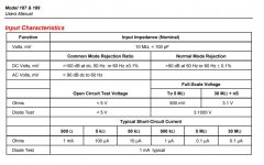
Input Z is far lower on 200mV AC range (or is it DC ranges?), than the 2V or 20V range, for example
That is incorrect. Here is the spec for one of the meters you cited. You will note that the input impedance is the same10Mohm on all mV and V ranges.
I suggest you SHOULD bother looking up this info before you post incorrect statements.
Attachments
So what would you suggest causes the phenomena,
Oh internet troll king?
(Check the DC specs)
P.S.
Data sheets are renowned for "stretching the truth"
Quoted from a number of calibration engineers....
(Yokogawa are about the only instruments, that I have spent time checking, which actually meet their data sheet accuracy; albeit with some complex mathematical caveats, clearly stated in the measurement conditions)
Funnily though,
The data sheet that came with mine, was a great deal more complex than that single sheet of blurb
Perhaps then, my 187 has a fault?
Key sight calibrated and yet...faulty?
😛
Last edited:
I mean...
Think about it....
10 MegOhm AC input impedance... across ALL frequencies in its capability of measurement?
Hmm. Ok...
Precisely...at 50 or 60Hz only.
Most interesting, is that you chose the obsolete 187 data sheet to quote, and not the 28II, which has frequency response and everything.
Mahooosive caveat
At 1kHz? What you think it is then? When measuring HT ripple/perturbation, in an amplifier, at maximum outputs with a stiff supply, requiring the use of mV scale?
Grow up, go talk like **** to someone, who doesnt know what they speak of.
Last edited:
considering that you have a speaker whose impedance varies all over the frequency range, connected to an output traffo to reflect every changing impedance to the plates, does it really matter?
Tony, this is a preamp. There is no speaker and no output trafo.😀
Most interesting, is that you chose the obsolete 187 data sheet to quote, and not the 28II, which has frequency response and everything.
Nope. I chose at random, but here is the 28II, same 10 Mohm input impedance on all mV and V ranges, ac and dc.
Attachments

Sorry for the digression. My point is that I agree with astouffer. The input Z of the DMM is not causing loading. And even if it was, a steady state additional load would not cause the voltage to fluctuate.
I was suggesting that poking around with DMM leads can cause momentary disturbances to a high Z circuit. Stray EM coupling, ESD and whatnot. And it's hard to predict how a digital display would react to those transients. This is why I suggest connecting a scope probe solidly and posting the trace so we can see what the fluctuation looks like. And preferably with the input shorted.
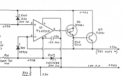
Oh, and read note 4. on that schematic.
I was suggesting that poking around with DMM leads can cause momentary disturbances to a high Z circuit. Stray EM coupling, ESD and whatnot. And it's hard to predict how a digital display would react to those transients. This is why I suggest connecting a scope probe solidly and posting the trace so we can see what the fluctuation looks like. And preferably with the input shorted.
Oh, and read note 4. on that schematic.
thanks for all the healthy debate and help.
I will switch it on and wait for it to warm up and then record a trace and try and upload it somewhere to share
🙂
I will switch it on and wait for it to warm up and then record a trace and try and upload it somewhere to share
🙂
so here is the link, hopefully it will work
I left it a lot longer on the anode than I have before and it did start to stabilise, so is this just the meter do you think?? also the B+1 is a lot more stable the other side of the anode resistor at the end, almost no fluctuation. Is this a weird effect of the meter on the circuit at the anode?
Shared album - Richard Palmer - Google Photos
If the supply end of the resistor is stable then its the tube drawing changing levels of current.
Last edited:
I edited my post. The b+ voltage is stable but the anode voltage is changing. That means the tube is drawing a proportional amount of current.
Tony, this is a preamp. There is no speaker and no output trafo.😀
ooppsss, sorry, senior moment...😀
No excuse needed as topic starter asks open questions without showing us an actual circuit. Same goes for a high voltage supply where B+ can be defined as existing before any regulator. Some more text explaining the situation is appropriate.
It is not unusual that a DMM changes the load to a circuit because of the extra capacitance and inductance involved, leading to changing operating conditions. If I stick the probe of my Fluke to a grid of a high amplifying stage this gives an audible signal of circa 0,5Hz. Checking anode voltage of a phase inverter with this Fluke one downloads the circuit, resulting in changing read outs. Not uncommon at all.
It is not unusual that a DMM changes the load to a circuit because of the extra capacitance and inductance involved, leading to changing operating conditions. If I stick the probe of my Fluke to a grid of a high amplifying stage this gives an audible signal of circa 0,5Hz. Checking anode voltage of a phase inverter with this Fluke one downloads the circuit, resulting in changing read outs. Not uncommon at all.
so since the voltage ultimately stabilises over a period to a final voltage with the meter on but quickly returns to the slow oscillation as soon as the meter is taken off and reconnected (disturbed again) then this is really a meter created issue and not some core instability in the circuit?

If the main b+ voltage isn't changing but the anode voltage is, that means the tube is changing how much current it draws.
Until you get some test equipment its all speculation. Download a frequency meter app for your phone and tell is what frequency the hum is.
If you put you meter on AC and read the main b+ what does it say?
Until you get some test equipment its all speculation. Download a frequency meter app for your phone and tell is what frequency the hum is.
If you put you meter on AC and read the main b+ what does it say?
just did it good idea 🙂
It's 50 hz through the speakers
tried the meter on AC from B+ to Earth and jumps about and does not settle on a reading
It's 50 hz through the speakers
tried the meter on AC from B+ to Earth and jumps about and does not settle on a reading
tonescout,
Often:
The AC bouncing is caused by Power Mains Line Bounce (different loads turning on and off at your house, and neighboring houses . . . water heater, electric heating, toaster, dryer, etc., and even further up the Power company's customers (closer to the original Dynamos that produce your power).
Try doing an AC reading of your power mains, does it bounce from reading to reading?
But often, power line bounce has shorter transient times than the time of a single DMM AC reading, so that test may, or may not work.
Line bounce is not Hum.
There are many causes of 50 Hz hum in the speakers.
Last edited:
- Home
- Amplifiers
- Tubes / Valves
- How stable should DC anode voltages really be?