I'm planning out a desktop headphone amp build, and I'm not sure how much space I need. How much distance should we put between a toroidal transformer and anything in the signal path?
I'm looking at getting either a 10 VA or 25 VA unit from AnTek. The 10 VA is 2.4" in diameter and the 25 VA is 3.0". With the 10 VA unit, I'd get about 60 mm (~2.4") of clearance between the transformer and the DAC board I'm using. Obviously less if I go with the 25 VA unit.
On top of that, I'm thinking of running either a line out or an aux in to the back panel, so that would cut into the clearance further.
Should I be considering any shielding options on the transformer as well?
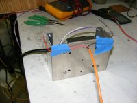
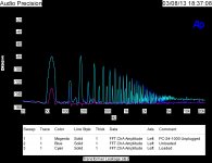
Attached is the flux leakage test set up to measure the voltage induced into the chassis, the leakage from a normal E-I transformer and the leakage from a similar size toroid.
You should mount you transformer is a shield and isolate it from the chassis with nylon standoffs for lowest noise.
0 dB is 1 volt as I recall.
You should mount you transformer is a shield and isolate it from the chassis with nylon standoffs for lowest noise.
0 dB is 1 volt as I recall.
Attachments

you could specify an interwinding screen and an external guass band.
Thanks. I have no idea what I'm looking for though.
Could I get away without any shielding at all? I have limited access to tools, so it would be easier if I could do without.
Interesting, which direction would you wind it?an external guass band.
General rule: there is NO general rule! Noise can come from magnetic and electric coupling too.
Toroidal transformers have theoretically no outside leakage flux, if the winding is distributed perfectly evenly, and if during the winding process of each coil the core rotates 0 in sum. The latter condition is often not fulfilled, hence the toroid transformer can behave like a 1...5 turn air core coil. Depending on the winding details a toroid can be almost perfect or as bad as an EI. This "rotation coil" flux can be cancelled by an inversely rotating wire, if you can measure the induced voltage.
If the wire is not evenly distributed, it is also a source of outside flux. For this I don't know simple remedy.
These fluxes decreases with distance, but since a tipical toroid main diameter is not very small, decreasing is not very fast, so avoiding interference by keeping clearance is not practical.
I suggest you to design a good layout instead, without ground loops, with symmetrical internal signal paths, signal and its reference wire as close to each other as possible. A good layout is not sensitive for magnetic disturbance.
Or you can simply measure the disturbance level around the transformer (under load!) with a probe coil and an amplifier.
General rule: there is NO general rule! Noise can come from magnetic and electric coupling too.
Toroidal transformers have theoretically no outside leakage flux, if the winding is distributed perfectly evenly, and if during the winding process of each coil the core rotates 0 in sum. The latter condition is often not fulfilled, hence the toroid transformer can behave like a 1...5 turn air core coil. Depending on the winding details a toroid can be almost perfect or as bad as an EI. This "rotation coil" flux can be cancelled by an inversely rotating wire, if you can measure the induced voltage.
If the wire is not evenly distributed, it is also a source of outside flux. For this I don't know simple remedy.
These fluxes decreases with distance, but since a tipical toroid main diameter is not very small, decreasing is not very fast, so avoiding interference by keeping clearance is not practical.
I suggest you to design a good layout instead, without ground loops, with symmetrical internal signal paths, signal and its reference wire as close to each other as possible. A good layout is not sensitive for magnetic disturbance.
totally agreed.
I might add that any DIY-metal shielding of the transformer is to no avail as these do not reduce the magnetic stray field significantly.
The only remedy is a very good pcb layout with minimized loop areas at the sensitive points.
Or replace the toroid by some smps.
Last edited:
Could you elaborate on what the sensor is, and where it is for the tests. Did you do any other tests to characterise the results, especially for the EI PT.Attached is the flux leakage test set up to measure the voltage induced into the chassis, the leakage from a normal E-I transformer and the leakage from a similar size toroid.
Could you elaborate on what the sensor is, and where it is for the tests. Did you do any other tests to characterise the results, especially for the EI PT.
As shown in the picture I mounted many different transformers to the same size chassis and measured the voltage induced along the length. From the data a torroid is 20 dB quieter than an EI.
Enclosing the transformer in its own box and mounting the box on insulated standoffs makes the induced voltage below simple measuring capability.
OK, thanks for clarifying. The sensor is likely to be the loop formed by the area between the wiring and the chassis, but also could be an earth loop formed by capacitance between the transformer windings and the measuring instrument.
Is the measuring instrument powered from the mains?
If you twist the sense wiring and only make one connection to chassis then what do you measure?
If you disconnect the sensing wires from the chassis, but form a loop with area in the loop then what do you measure?
Is the measuring instrument powered from the mains?
If you twist the sense wiring and only make one connection to chassis then what do you measure?
If you disconnect the sensing wires from the chassis, but form a loop with area in the loop then what do you measure?
OK, thanks for clarifying. The sensor is likely to be the loop formed by the area between the wiring and the chassis, but also could be an earth loop formed by capacitance between the transformer windings and the measuring instrument.
Is the measuring instrument powered from the mains?
If you twist the sense wiring and only make one connection to chassis then what do you measure?
If you disconnect the sensing wires from the chassis, but form a loop with area in the loop then what do you measure?
The device under test is powered from an isolated clean sinusoidal power source. The cable is taped to the chassis to minimize and standardize the test. The cable is twisted shield pair typical West Penn Wire 291.
Please note the baseline curve with the transformer unplugged.
I did these tests years ago.
Now one for you. Some folks claim that if your gear has two prong plugs, flipping them over can change the sound. Why?
Just trying to get more of an insight in to what your results are actually measuring 🙂
Swapping the mains input phasing could have many subtle influences. So too can swapping the heater phasing (but not the mains side phasing). It would depend on what hum paths and asymmetries are significant. Sometimes a humdinger pot has no effect, and sometimes an asymmetrical setting is an improvement. For example, a mains side active wire is near enough to input circuitry to have an influence, and so changing that wire to a neutral wire causes a drop in hum.
Swapping the mains input phasing could have many subtle influences. So too can swapping the heater phasing (but not the mains side phasing). It would depend on what hum paths and asymmetries are significant. Sometimes a humdinger pot has no effect, and sometimes an asymmetrical setting is an improvement. For example, a mains side active wire is near enough to input circuitry to have an influence, and so changing that wire to a neutral wire causes a drop in hum.
- Status
- Not open for further replies.
- Home
- Amplifiers
- Power Supplies
- How much clearance around a toroidal transformer?