would there be a rough approximation of the ear canal involved and if so how might that look? (stepped horn? - sidebranch?)
just the low end is really the concern.
Here's a Tymphany 50mm frame driver mentioned at Head-Fi - Vas is very high and fs very low for such a thing

just the low end is really the concern.
Here's a Tymphany 50mm frame driver mentioned at Head-Fi - Vas is very high and fs very low for such a thing
Hi ?Chris - perhaps 0 pi would predict with a perfect seal between driver and one's head ??
(maybe David will comment)

(maybe David will comment)
Hi ?Chris - perhaps 0 pi would predict with a perfect seal between driver and one's head ??
(maybe David will comment)
Hi Fred,
Selecting the Ang = 0.0 x Pi option in Hornresp specifies an infinite horn. For your example, this means that the acoustical load on the "ear" side of the driver diaphragm is assumed to be equal to the throat impedance of an infinite-length cylindrical horn of cross-sectional area 3 cm^2.
Kind regards,
David
Hi ?Chris - perhaps 0 pi would predict with a perfect seal between driver and one's head ??
(maybe David will comment)
Yep, I expect so.
You could still introduce the ear canal as a 4th order bandpass.
Chris
Hi David and Chris
might there be a practical way to roughly estimate a headphone's potential LF as an average of infinite and finite conditions?
Here's an interesting paper concerning measurement of IEM
https://tikander.net/miikka/Science/Publications_files/hiipakka04_JAES.pdf

might there be a practical way to roughly estimate a headphone's potential LF as an average of infinite and finite conditions?
Here's an interesting paper concerning measurement of IEM
https://tikander.net/miikka/Science/Publications_files/hiipakka04_JAES.pdf
Last edited:
might there be a practical way to roughly estimate a headphone's potential LF as an average of infinite and finite conditions?
Hi Fred,
I would be surprised if there is, but as this is way outside my area of "expertise", I don't really know 🙂.
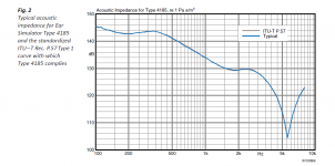
The attached chart shows the acoustical impedance of the human ear under sealed conditions, as used in the Brüel & Kjær Ear Simulator for Telephonometry Type 4185. This gives a completely different result to that obtained assuming an infinite cylinder for the ear canal.
Kind regards,
David
Attachments
freddi - what is your query all about?
And don't forget the El Greco fallacy
El Greco fallacy - Wikipedia
Is what you are asking like somebody suggesting eyeglasses to invert the image so they wouldn't be upside-down on your retina?
And don't forget the El Greco fallacy
El Greco fallacy - Wikipedia
Is what you are asking like somebody suggesting eyeglasses to invert the image so they wouldn't be upside-down on your retina?
I would like to get an idea from headphone drivers with published T&S # - but for my own curiousity the mess below

T/S isn't a universal truth. It is just a simplified (or too simplified) model of a generic Rice-Kellogg driver in free air intended for easy calculation (and which can also be applied in figuring the effects of "enclosures"). Even if you could generate the numbers for the drivers in your headphones, the model would apply at best only loosely to that setting.
1. Perhaps what you want is to start with a listening chair of known REW FR.
2. produce your hearing results from that chair (you can do individual ears using an ear plug)
Online Hearing Test & Audiogram Printout
3. repeat with the headphones under examination
1. Perhaps what you want is to start with a listening chair of known REW FR.
2. produce your hearing results from that chair (you can do individual ears using an ear plug)
Online Hearing Test & Audiogram Printout
3. repeat with the headphones under examination
Last edited:
Wow. I have some of those Faital drivers, can't say I'd want to hang them on my ears. 😱 Even tho I do own same rather large headphones. You're a brave man, Freddi.
In my experience with headphone design and testing at low frequencies (where the wavelength is much longer than any dimension of the cavity) its a pressure vessel. You can see that in the test of different length cavities. The longer cavity below 1KHz has about the same curve and lower spl when the space is larger. Since most of this range is below resonance the TS parameters are sort of useful for predicting sensitivity, however the earcup and the ear cushions will have a major impact on sensitivity and response and are not easily modelled. Many headphones have a resistive connection between the earcup and the ear cavity that is used to tune (boost) bass.
Another big issue with headphone drivers and bass is compression at lower frequencies. Above about 95 dB on many headphones the bass stops increasing in pace with the input. The driver diaphragm is bending from the pressure. Thicker diaphragms that don't do this have limited treble response.
Another big issue with headphone drivers and bass is compression at lower frequencies. Above about 95 dB on many headphones the bass stops increasing in pace with the input. The driver diaphragm is bending from the pressure. Thicker diaphragms that don't do this have limited treble response.
- Status
- Not open for further replies.
- Home
- Loudspeakers
- Subwoofers
- How might one best fudge a headphone's LF with hornresp?