I noticed that in the early Fender tube amps lots of times they'll have a resistor off the grid to ground in the preamps. How is the value of this resistor chosen? I've seen values from 1Meg to 10Meg. Once the value is chosen, how do you know the grid is at the right voltage?
Based on the datasheet for the tube (12AX7), the grid voltage appears to affect the idle (Q) point of the tube. So I would think the value of this resistor matters in some way.
Based on the datasheet for the tube (12AX7), the grid voltage appears to affect the idle (Q) point of the tube. So I would think the value of this resistor matters in some way.
That actually creates more questions than it answers. I had typed up a huge reply but for some reason this stupid site automatically logged me out and I lost it. This is the second time. Basically, when cathode biasing a tube you set the plate current and plate voltage, right? You'll also have a load line with a specific point somewhere on it, based on plate current and plate voltage. Now looking at the transfer characteristic graph
https://www.jj-electronic.com/images/stories/product/preamplifying_tubes/pdf/ecc83s.pdf
You will magically arrive at a grid voltage, regardless of grid-leak resistor. Does that sound correct?
Now if I add a grid-leak resistor of, lets say 1 Meg ohm, will that affect the bias point previously set?
https://www.jj-electronic.com/images/stories/product/preamplifying_tubes/pdf/ecc83s.pdf
You will magically arrive at a grid voltage, regardless of grid-leak resistor. Does that sound correct?
Now if I add a grid-leak resistor of, lets say 1 Meg ohm, will that affect the bias point previously set?
The grid current is extremely small in a typical self biased stage and so the actual value of resistor used has no real effect on the DC operating point. In other words the grid to cathode potential is the same whether you use 10k or 1 meg.
Using high values such as 500k and upwards minimizes loading on the stage driving the grid and also allows for smaller value coupling caps.
Using high values such as 500k and upwards minimizes loading on the stage driving the grid and also allows for smaller value coupling caps.
1Meg is the 'standard' value for preamp work. You can always go smaller, but you generally only use a larger value if you absolutely need a higher input impedance, or you have a box full of 3.3Meg resistors that you want to use up!I noticed that in the early Fender tube amps lots of times they'll have a resistor off the grid to ground in the preamps. How is the value of this resistor chosen? I've seen values from 1Meg to 10Meg.
There is a maximum value that you should not go above, because it can lead to unreliable or drifting bias. It is not always stated for preamp valves, which is why we default to the safe, comfy value of 1Meg. But up to 10Meg is usually OK for valves running at low currents (<5mA).
Power valves are different since they run at high currents and mistakes are expensive. They have stricter grid-leak limits stated on the datasheet.
Unless there's something wrong with the tube it's unlikely that there will be anything wrong with the grid voltage. So you just assume it is 0V unless you discover the circuit is producing strange anode/cathode voltages that raise your suspicion.Once the value is chosen, how do you know the grid is at the right voltage?
You won't often see grid leak values between 1M and 10M. This is because 1M is about as high as you can go and still keep the grid near zero volts - the bias then being applied at the cathode.
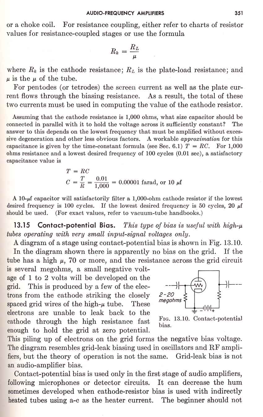
If, on the other hand, you want to use grid leak bias (sometimes called contact potential bias) then you need a resistor around 10M.
If, on the other hand, you want to use grid leak bias (sometimes called contact potential bias) then you need a resistor around 10M.
The grid leak is there basically to keep it 0v, that is in a cathode biased setup, as others have said 1M is usually the prefered value and often with a 0.01u cap. On the Mullard ECC83 datasheet resistor values etc for just about every DC condition is given, so there's no real working out needed.
Andy.
Andy.
It´s an **old** trick to bias Tubes and save 1 resistor and 1 capacitor.I noticed that in the early Fender tube amps lots of times they'll have a resistor off the grid to ground in the preamps.
Way back then, parts were expensive !!!!
You decide on what bias voltage you need for chosen operating point, then multiply grid current by grid resistor which is chosen to drop that voltage.How is the value of this resistor chosen?
Youcall it "chosen", I´d prefer to call it "calculated", although absolute worst case you can find it experimentally.I've seen values from 1Meg to 10Meg. Once the value is chosen, how do you know the grid is at the right voltage?
Given that grid current varies from tube to tube and old time resistors varied by 20% , even more very high values as involved here, you had a a little of a lottery game running.
You can NOT measure grid voltage, because meter resistance will wreak havoc with that, but you may read plate voltage, which after all is the desired end result.
Of course, the point of the datasheetis showing that.Based on the datasheet for the tube (12AX7), the grid voltage appears to affect the idle (Q) point of the tube.
You bet.So I would think the value of this resistor matters in some way.
The grid current is extremely small in a typical self biased stage and so the actual value of resistor used has no real effect on the DC operating point. In other words the grid to cathode potential is the same whether you use 10k or 1 meg.
Using high values such as 500k and upwards minimizes loading on the stage driving the grid and also allows for smaller value coupling caps.
Thank you, this is the point I was trying to understand.
Thanks for the replies, this is starting to make sense. So when a tube is cathode biased, the grid voltage is slightly below ground (due to electrons smashing into the grid and the small grid-leak voltage) and a number of volts below the cathode (due to the current through the cathode resistor), correct?
If this is true, the grid to cathode bias voltage is technically the cathode voltage (Ic*Rc) minus the small negative voltage at the grid (produced by electrons hitting the grid and the resulting current flow to ground through the grid-leak resistor). So slightly larger than expected. All with respect to ground.
Is this the same principle for the grid-leak bias?
On an early model of the Fender Deluxe, the first tube (6SC7) used a grid-leak bias. The cathode was tied to ground and the grid had a 5 Meg resistor to ground. This would bias the tube only slightly negative, correct? Effectively near the saturation and clipping region (Eg = 0) of the tube from my understanding. The slight bias is due to the electrons heading toward the plate and smashing into the grid along the way, correct?
https://robrobinette.com/images/Guitar/Deluxe_Models/5C3_Schematic_Signal_Path.gif
https://frank.pocnet.net/sheets/093/6/6SC7.pdf
Also where do you find the datasheets for Mullard tubes? They appear to be owned by New Sensor Corporation (Mike Matthews of EHX) now.
Last edited:
Another interesting point is if the grid-leak resistor is left off or too high. From what I understand, charge buildup occurs on the grid. The electrons at the grid repel electrons coming off the cathode. This effectively reduces plate current. I'm guessing it makes the grid more negative as well.
My question is, does the charge buildup at the grid actually flow through the grid resistor making the grid more negative or do the electrons get stuck there at the grid and effectively reduce the electric field the electrons heading toward the plate are traveling through.
Base on physics, a space charge electron cloud is created off the cathode from due to the heating of the cathode by the filament. An electric field is then created from the electron cloud to the positively charged plate. I wonder if the electron buildup at the grid, when open or grid-leak is too high, essentially forms another electron cloud which affects/reduces the field between the cathode electron cloud and positive plate.
Last edited:
If, on the other hand, you want to use grid leak bias (sometimes called contact potential bias) then you need a resistor around 10M.
This is just what I needed, I looked up contact potential bias and ran across this. The light bulb went on finally. 🙂
Fusing and Floating Grids
In a contact potential bias the electrons pile up and the grid becomes more negative. This makes complete sense now.
You asked about datasheets for Mullard valves. These are available online from several sources, although many may be labelled Philips - assuming you mean real NOS Mullards, not the modern Russian-made valves which just happen to bear the same brand name. Just Google the European name for the valve (e.g. ECC83).
My go-to site for tube datasheets usually is Frank Philipse's site:
Frank's Electron tube Pages
Or, directly to the data sheets:
Frank's electron Tube Data sheets
Have fun, Claas
Frank's Electron tube Pages
Or, directly to the data sheets:
Frank's electron Tube Data sheets
Have fun, Claas
Amplifying all the above:
Grid current is normally much smaller than any other current in an amplifier. Therefore we can use a "large" resistor, which does not load-down most sources, and still have the grid voltage "zero" for practical purpose.
Grid current is rarely given in data. And I disagree we can casually measure it and get a full picture. It varies a LOT with operating point. It varies between different tubes, batches, brands, and vintages. It will normally be "high" when you take it out of the box and decline over a few days of hot operation. Most meters will leak as much as a grid.
But for a small triode at small plate current, pencil '50 nA'. Put that in 1Meg, we have 50mV or 0.050V. What is the grid-cathode voltage needed for normal operation? Often 1V or 2V. A 0.050V uncertainty on a 1-2V bias is not important.
See Radiotron Designer's Handbook, 4th Edition, section 2.2 (snip attached).
Also notice that the plate resistor has a major effect on operating bias. If the tube tends to suck more, plate voltage drops, it sucks less. Same if you have a cathode resistor.
OK, go up from 1Meg. 10Meg seems to give 0.5V of grid voltage. This is a useful bias and operating point for *small* signals. It gives nearly maximum gain. It is fairly stable because if plate-cathode current increases, grid-bump current increases, grid goes more negative, plate-cathode current decreases. All fairly sensitive to grid treatment and gas content, so the operarting point is not well-defined, but with proper choice of RP is is real sure to work for small signals. And it maximizes input impedance. (However the dynamic impedance may be half of the obvious 10Meg due to grid current acting as a parallel resistance.) And it avoids using a cathode bypass cap which was a real trouble-spot in older electrolytics.
All the above is for small triodes at small currents. And note that typical circuits with hundreds of volts and hundred-K plate resistors can't "burn up" even if the grid goes way positive. If the tube hogs current, large RP drops plate voltage, maximum current is easily figured and rarely dangerous.
When you have a BIG HOT tube, especially with a transformer (low DCR), it is possible for grid current to *reverse*. It may, at switch-on, go negative and the tube biases "near dead". But a large signal may reverse the grid current and drive the grid +positive+. Tube current soars. There's no large plate resistor to set any real limit. Power tubes with missing or too-large Rg *can* burn up pretty quick.
Most tubes have a "maximum grid resistance". This is conservative. It covers a bad day in the tube factory and a near-limit operating point. 98+% of well-made tubes can go much higher. We sometimes cheat the limit. On 12AX7 in reasonable circuit, no harm can happen, it just won't sit at the op-point we plotted; but it may sit near-enough there for all the tubes we put in the socket. A transformer loaded 6L6 sure can cook itself, and fix-bias class A is about the worst case. These amps "must" hew to the 100k max. However many Fenders get-away with 220k, because they are biased "cool AB", and a shift of grid voltage merely moves the op-point to a less-cool AB. (And also because for years Fender was getting very-good tubes by the crate.)
Attachments
Last edited:
So when a tube is cathode biased, the grid voltage is slightly below ground (due to electrons smashing into the grid and the small grid-leak voltage) and a number of volts below the cathode (due to the current through the cathode resistor), correct?
Strictly speaking it is the role of the grid leak resistor to keep the grid at ground potential. The cathode resistor puts the cathode at a positive potential to ground. Input voltage is measured between cathode and grid.
- Home
- Amplifiers
- Tubes / Valves
- How is the grid leak resistor chosen?