A compression driver has to have two peaks, but any more than that is proof that diffraction has occurred in the device somewhere.
aha ... so we also have HOM inside the driver itself

and these appear as the small impedance 'ressonances' we often see on many kinds of drivers in general ?
Why is it that people just don't read what I write. I specifically said that HOM from the driver WILL NOT appear in the impedance. 🙄 The "device" in the quote above is the waveguide not the driver.
I hope the attachments works. It shows what would need to be made. The radius could be +-10% without a problem.View attachment Waveguide.pdf
I hope the attachments works. It shows what would need to be made. The radius could be +-10% without a problem.View attachment Waveguide.pdf
Last edited:
I hope the attachments works. It shows what would need to be made. The radius could be +-10% without a problem.View attachment 395789
..The pdf shows some sort of egg shape, is this correct or just a drawing error?
Furthermore, shouldn't the connection between waveguide and sphere be smoother?
Kees
Why is it that people just don't read what I write. I specifically said that HOM from the driver WILL NOT appear in the impedance. 🙄
It could be that you changed what you had written from the time he pulled your quote.
In fact I couldn't find the quote he used from you. (..perhaps another post?)
-why get upset over it? 😕
It's easier to simply "re-quote" your own quote that provides the needed information. (..it's that multi-quote button with the " in the bottom right.) No additional typing required.
Last edited:
It could be that you changed what you had written from the time he pulled your quote.
In fact I couldn't find the quote he used from you. (..perhaps another post?)
-why get upset over it? 😕
It's easier to simply "re-quote" your own quote that provides the needed information. (..it's that multi-quote button with the " in the bottom right.) No additional typing required.
A couple of clarifications here.
First, I did not start this thread, but being the expert on HOMs I thought it advisable to comment.
I am not an experimentalist, I am a theorist. I do not have a lab or any real way to do measurements. I can clear my living room of furniture and make some measurement in there from time to time, but I need to be in and out fast (I do not live alone!!) I cannot set up to do ongoing research. So there is no way that I am personally going to ever make measurements of HOMs. People who use this fact to claim I am dodging the issue are simply being disingenuous.
Someone asked "Why do we care about HOMs". I CARE because without them we cannot have a detailed mathematical description of how horns work. They exist, and are always present, that much is irrefutable and has been proven by Markarski. I showed how they had to exist mathematically and he showed that they do in fact exist. So let's put that part to rest.
How audible are they? I personally have never made any claims on this either way. I showed how HOM like signals have some very unique characteristics that meld very well with subjective aspects of horns. This is not proof, I have never claimed it was (physics can never prove something is true, it can only prove something is not true. No one has proven that what many hear as poor sound in a horn, and many many do, is NOT HOMs.)
Diffraction in a horn and HOMs are not different things, they are the same thing. When a wave propagates down a horn and reaches a discontinuity two things happen. The first is that some of the wave is reflected from this junction back down the device and impinges on the diaphragm. It many cases we can see this effect in the impedance curve. The second is that the wave going forward is diffracted. Now this diffraction has two components. The first is in the shape of the main mode and we simply call this the transmitted wave. It would not be proper to call this portion of the wave "diffraction". However, the diffraction does generate waves that do not move down the axis of the device but at angles relative to it. These waves are, by definition HOMs. So you can see that diffraction and HOMs are really the same thing - they are not separable in either measurement or theory. The reflected wave is separable but yet it still gets mixed up with the main wave and the diffracted wave after these leave the device.
But this still isn't a complete picture because HOMs exhibit cutoff. This is when the wavenumber of the diffraction is imaginary and the wave decays exponentially rather than propagates. These are called evanescent waves. Depending on the distances involved these waves can completely dissipate by the time the wave exits the device, but that is not guaranteed. Some of these evanescent waves could reach the mouth of a short device.
Diffraction at the mouth is unique in that the diffracted wave is now in free space and as such all wavenumbers are allowed. So mouth diffraction is a kin of HOMs, but being as they are in free space they do not exhibit cutoff. The reflected portion of the mouth propagates back down the device and can sometimes be seen in the impedance curve. A compression driver has to have two peaks, but any more than that is proof that diffraction has occurred in the device somewhere.
If the wavenumber is high enough, then it becomes real and this wave will propagate down the device reaching the mouth and propagate out into space, but it will always follow behind the main wave in time - a tail if you will. But this is also true of the reflected wave that moves back down the device after reflecting off of the diaphragm. The delay times would be quite different however.
It is my opinion that only the main non-diffracted or reflected wave is desirable. All other aspects are aberrations and undesirable. How do we weight the relative audible effects of them? That is completely unknown and would be a massively complicated problem to take on. Hence my approach is and always has been to reduce all of these effects as I simply do not know which is which and how audible any of them are. I do believe, and there is no doubt in my mind about this, that reducing them all yields a far preferable device. Again, this cannot be proven, but no one has proven that it is not true either. All of the evidence says that it is true. None that I know of refutes it.
And all that IS science.
..and of course, using a bold or italic modifier to indicate the pertinent area of the quote works well. 😛
..The pdf shows some sort of egg shape, is this correct or just a drawing error?
Furthermore, shouldn't the connection between waveguide and sphere be smoother?
Kees
It is a perfect sphere of the indicated radius with the waveguide embedded inside, just as I said. This is strictly for measurement purposes not for listening. Yes there will be diffraction at the sharp edges, but the calculations will know about this and it won't be a problem.
In my above description I forgot to mention that HOMs could originate from the driver itself and according to Makarski this is the major source. I have no trouble believing that for a waveguide in which an attempt has been made to minimize the inherent internal diffraction of the connect horn. But I cannot see that being the case where there is intentional diffraction along the waves path. An easy test is to look at the impedance curve. If you see any sign of more than two peaks then there is internal diffraction and one cannot conclude that the source is the major culprit. But if the system, as mine do, has only two peaks with no signs of any other peaks (< 10 kHz) then it is reasonable to assume that the driver could be the major source because driver generated HOMs would not show any impedance aberrations.
Not in the original post agreed. But before the incorrect post.
 ..works.
 is a driver not like a small horn itself ? ... why would it not cause any impedance variations ?
I once asked a supplier why there was a wriggle in the impedance response of one of there drivers, the response was there was a change in driving power at that frequency, so I also assume that driving the driver with difference signal sweeps might also create some funny wriggles, I know that some that happened in some of my tests were due to ADC/DAC clock issues. Really depends on the exact shape and frequency with cross examination to determine the true cause.In my above description I forgot to mention that HOMs could originate from the driver itself and according to Makarski this is the major source. I have no trouble believing that for a waveguide in which an attempt has been made to minimize the inherent internal diffraction of the connect horn. But I cannot see that being the case where there is intentional diffraction along the waves path. An easy test is to look at the impedance curve. If you see any sign of more than two peaks then there is internal diffraction and one cannot conclude that the source is the major culprit. But if the system, as mine do, has only two peaks with no signs of any other peaks (< 10 kHz) then it is reasonable to assume that the driver could be the major source because driver generated HOMs would not show any impedance aberrations.
Actually it can.is a driver not like a small horn itself ? ... why would it not cause any impedance variations ?
I have access to a 2.4 x 2.4 M flat baffle, but it is sort of designed to accommodate drivers of different sizes for half sphere measurements.Hi Paul
...
If someone built a big baffle, say 8 foot square, put a round waveguide in it and did polar measurements at say every 2.5 degree all the way from the normal to the baffle (90 degrees) at 1 meter, then I would have some data to work with, but no guarantees that anything would come of it. This is hardly a trivial task for not much guarantee - that's what research is all about. No company is going to do this - none that I know of at least. We started this at B&C but the project was never competed. Would have been interesting.
Oh and by the way, the modes that one gets from the flat round aperture are not the same modes as inside of the waveguide. So one has to find a transform from one set to the other. This is common in physics, but numerically how stable it is another unknown. With a spherical baffle the modes in the device are the same as the modes on the sphere so there is no transform required. That's why I thought of the sphere at first. Anybody got an eight foot sphere?
There is a pretty big sphere dome made of fiberglass in a religion museum here.😀

A while back, an organization was considering getting rid of a 20ft dome, but it is smooth on the inside instead.
Last edited:
is a driver not like a small horn itself ? ... why would it not cause any impedance variations ?
An HOM can be created by an improper phase plug for example (non-uniform channels) and hence there is no reflected wave in that case and no impedance glitchs. If the driver is not well matched to the horn or there is no horn then there will be reflections and there will be a noticeable glitch on the impedance cure.
Regarding the test methodology, wouldn't the angle at which the waveguide is 90 degrees (as if it were flush to the baffle) have an edge where it joins the sphere? Wouldn't a large torus be much better as this limitation wouldn't exist?
The edge diffraction is part of the system that is modeled. If you change it then the model is no longer valid. A torus is possible, but the wave functions are much more complicated. A sphere has well know functions. Ones that I already have the numerics for.
In development work, it makes sense to first take care of design from driver input to the part prior to free radiation. This part is actually more dominant in drivers in its influence on direct sound.
I know this thread has been dead for a long time now but I can't help being curious: were the measurements being discussed by Kees and Earl ever actually performed?
Hmmmm...
So far as I can tell, HOMs occur when sound bounces around inside the horn, instead of moving along the horn axis as you'd expect.
Given that, it would be possible to mount the driver to the horn, and then send clicks (1 sample wide) to the driver, and then record the result.
Look at the recorded trace, and see if there are reflections or smearing of the impulse signal.
I've just given that a try, and will figure out a way of uploading the results in a way that'll let you guys experiment.
Chris
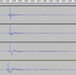
Okay, here goes.
Files are as follows:
- screencap from Audacity, trimmed to a single recorded click.
- Impulse file (44.1kHz sample rate, 1 sample up as a click)
- Raw compression driver
- On-axis with horn
- Off-axis with horn
- Mic put somewhere around 2/3rds of the way into the horn
Mic was a Beyerdynamic MM1, soundcard was a Behringer UMC202HD. Compression driver is a 18Sound ND1460, horn is an RCF HF94.
Chris
EDIT - change .asc to .wav to get the files working.
Attachments
Last edited:
- Status
- Not open for further replies.
- Home
- Loudspeakers
- Multi-Way
- How is HOM measured?