I only get results nowhere near what it should measure. (i might still be loading it to hard when measuring.
)so my question what amount of Mega Ohm would be ok for R1 and R2

I now used R1 12M and R2 220M.
but all measurements i did , do not come close to the stated Bias, example a 2.5Kv bias from er audio gets me only 800 volt 🙂 so clearly i might not use high enough values ? or is it broken, its pretty annoying to troubleshoot if your measurement is so far off 🙂
)so my question what amount of Mega Ohm would be ok for R1 and R2
I now used R1 12M and R2 220M.
but all measurements i did , do not come close to the stated Bias, example a 2.5Kv bias from er audio gets me only 800 volt 🙂 so clearly i might not use high enough values ? or is it broken, its pretty annoying to troubleshoot if your measurement is so far off 🙂
Attachments
R1 10 gigaohm should be OK. It should be specified for the voltage to be measured (10 kV?). About 8 to 10 cm long resistor built in a plastic tube.
I have a 9 gigaohm resistor that I built in an overlay pen plastic tube with a wire tip. The other end is a long wire with a banana plug, goes directly to my DMM that has 10 Mohm input resistance.
I have a 9 gigaohm resistor that I built in an overlay pen plastic tube with a wire tip. The other end is a long wire with a banana plug, goes directly to my DMM that has 10 Mohm input resistance.
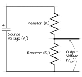
Your results are pretty typical when attempting to measure ESL bias. Since the source is high impedance, with very low current output, attempting to measure usually leads to much lower measured voltage. Also note that the input impedance of your meter (perhaps 10-Mohm?) will likely swamp out any voltage divider action of R2.
For example, when measuring the bias on an Acoustat ESL, with its 500 M-ohm outfeed resistor (R1 in your schematic), even a proper high-impedance, high voltage probe (R2 in your schematic) will measure more like 3.5-kV instead of the theoretical 5-kV.
The above post will get you much closer to the theoretical value, as the impedance is higher than a typical HV probe. But you’ll still probably measure less than theoretical voltage due to loading of the supply.
thank you guys ! so it looks hardly possible to get an accurate reading with a cheap meter and a voltage divider... 🙁 well the HV seems to be working i just miss like 8 dB, witch might well be something else like to good to be true specs 🙂 or something else. (also because both panels are exactly the same, chance both HV are broken is less likely)
i was measuring a ER audio Kit the old 440 kit. and after making it flat (in the dsp). i am left with only 80 db or something maybe even less. spec sheet says 88dB. although i wonder if thats possible with such an open frame (not much copper there and huge slots that are undriven in my opinon)
so i am afraid that spl might have been measured without filtering out the rising response..... making it useless
I once built a hv prope using 46 x 22M in series to 1M, so around 1 gigaohm input. When measuring esl bias with this, the initial reading comes close but it drops quickly due to the load. So 10 gigaohm is probably more in the range for reliable measurements yes.
Beware of the voltage ratings of the resistors, most become rather non-lineair above 2-300V.
Could it be the coating is going bad? That could ruin sensitivity for sure. Very long charging times can point in that direction, so does varying loudness over the membrame area. I always do the breathing test. When you breath on the membrame the moisture in your breath will decrease the surface resistance of the coating temporarily. If that results in increased output, the resistance of the coating has become too high.
Other possibility is the panels are leaky. How long does it take for the output to drop after switching the bias off?
I guess you seen the video ?if not its this panel, witch apparently is not made by ER audio. (they asked me to remove there name)
now i did some measurements and spl wise this is what i get picture 2
-Brown without any filter (its around 88db at 10khz
 ) but only 73dB at 500hz
-Green with some filtering (to counter the rising response), but to be usefull down to 300hz it should even be filtered more. witch would result in even less spl

original spec sheet said


now i did some measurements and spl wise this is what i get picture 2
-Brown without any filter (its around 88db at 10khz
-Green with some filtering (to counter the rising response), but to be usefull down to 300hz it should even be filtered more. witch would result in even less spl
original spec sheet said
Attachments


I'm measuring Beveridges so my impedances are different. But I use a 100M resistor loaded with 1Meg to ground. It's a scope probe.
Here's my take on the same issue https://www.diyaudio.com/community/...-beveridge-otl-amplifier.405015/#post-7496315
Another possibility is to get one of the old Fluke 80K-40 HV probes, I think it has a 999 Meg R in it?
Here's my take on the same issue https://www.diyaudio.com/community/...-beveridge-otl-amplifier.405015/#post-7496315
Another possibility is to get one of the old Fluke 80K-40 HV probes, I think it has a 999 Meg R in it?
So did you measure the coating resistance on the diaphragm on both transmitters or just one?I guess you seen the video ?if not its this panel, witch apparently is not made by ER audio. (they asked me to remove there name)
now i did some measurements and spl wise this is what i get picture 2
-Brown without any filter (its around 88db at 10khz) but only 73dB at 500hz
-Green with some filtering (to counter the rising response), but to be usefull down to 300hz it should even be filtered more. witch would result in even less spl
original spec sheet said View attachment 1230534
View attachment 1230532
You have a good insulation resistance meter, it must be about 60 years old😆?
I think you should disassemble both transmitters, select the same areas on them and measure them with probes, and measure the entire membrane area in the same way.
If the resistive coating has degraded in some areas, you should change the diaphragms on both transmitters.
In general, when such a problem arises, that the coating suddenly "goes away", - it means that the manufacturer is not good-known to his work, because even I in my garage make the coating, and then fix it with a special varnish with thermal treatment so that both materials (varnish and Mylar) are glued forever, and therefore the resistive coating on Mylar is preserved for life.
Displacement voltage and resistance of the membrane coating are interrelated, if the coating is "vaporized" on some parts of the membrane, there will be a failure in the output of certain frequencies, in particular high frequencies.
are you making fun of me 😉 hehe im sure i said dumber things in this video hahaWing nut 🙂
since the subject has been a while ago and i made to many assumption... better stick with my planar magnetics haha. anyhow ill try give it a recoat. not much to lose so.
Yeah i removed it, since, i made a few assumption about ER audio been involved in the panels (i should not jump to conclusions to fast). while they might help out in some parts of the design, its was produced by another company. just dont want to spread wrong information/me saying things that aint true.I see: "This video is private"
I redid the coating, with the ER audio coating (looks allot like Licron crystal from a jug) Rob from ER did warn me the coating bottle i had might not work anymore since it is old. so far it charges fine, but i measured exactly the same output spl. not a big surprise since i measured the original coating and it seemed fine to.
then whats left is the stator itself. but since it is painted black or something, i cant see how big of a percentage of the PCB is actually conductive. (and since the slots are already rather big there might not be enough stator left to drive it properly ??) its the only thing i can think of why the output is so low. i measured the transformer and its a decent 1:100 ratio, should work fine.
then whats left is the stator itself. but since it is painted black or something, i cant see how big of a percentage of the PCB is actually conductive. (and since the slots are already rather big there might not be enough stator left to drive it properly ??) its the only thing i can think of why the output is so low. i measured the transformer and its a decent 1:100 ratio, should work fine.
hehe yeah i could not find the correct word for it hahaep.. vleugelmoer
diyAudio member mats31 suggested a method to get an accurate measurement of the HV multiplier output using 2 separate voltage divider values that don't have to be 1000s of Megohm. The basic concept goes back to highschool algebra...(ie 2 equations, 2 unknowns). https://www.diyaudio.com/community/threads/quad-esl-57-power-supply.335548/post-5745206thank you guys ! so it looks hardly possible to get an accurate reading with a cheap meter and a voltage divider...
The behavior of a HV multiplier is that of a HV source with a rather larger source impedance in series with it.
You can calculate this source impedance using formula provided below.

If you measure the output using a voltage divider and DVM with two different values for R1, you can the calculate the HV source voltage and impedance.

I also attached below a spreadsheet to perform these calculations if you don't find math fun.
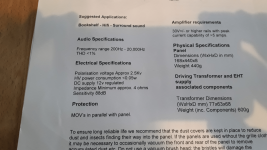
It is certainly true that if the stator openings are large compared to the airgap between stator and diaphragm you will lose efficiency.although i wonder if thats possible with such an open frame (not much copper there and huge slots that are undriven in my opinon)
If you are able to measure the capacitance between the stators and provide the dimensions of the panel stators and airgap, you can actually estimate how much efficiency is lost.
Details here: https://www.diyaudio.com/community/threads/first-time-esl-builder.246846/post-3881204
I don't think the ~80dB you are measuring is unreasonable for that size of panel with 2.5kV bias and 100:1 transformer. I'd estimate about 84dB @ 1kHz as about the best you could expect. Perhaps the 88dB value in the specifications is an "equivalent" efficiency at typical listening distance of 3m or so compared to a point source.
Attachments
Last edited:
Hmm thats a good one ! 88 dB calculated back to 1 meter is not exactly fair , so Rob from ER said they might used noise at 3 meter away, then calculated it back to 1 meter (and if they used 3 db for all frequencies........ its a fail). , if thats what happened they went for the 3 dB loss for all frequencies ... while ignoring all frequencies that dropped 6 dB. making it completely unbalanced if you want to cross it that low.I don't think the ~80dB you are measuring is unreasonable for that size of panel with 2.5kV bias and 100:1 transformer. I'd estimate about 84dB @ 1kHz as about the best you could expect. Perhaps the 88dB value in the specifications is an "equivalent" efficiency at typical listening distance of 3m or so compared to a point source.
thanks for the measuring method. i have to look at is a bit better to see whats going on.!
Last edited:
ill try measure the capacitance ! so if it measures the right value compared to an ideal capacitor of the same dimensions. it should be fine i asume ? and would make it clear if there is enough area driving it 🙂 thats a really simple idea !! thanks bolserst !!
i need to get them appart first to get the DC spacing 🙂 also i cant actually see the true DC spacing. since everything is black. im not sure if the copper is on the inside or the outside. (i asume inside since there is a solder point for the stator connection on the inside)
i need to get them appart first to get the DC spacing 🙂 also i cant actually see the true DC spacing. since everything is black. im not sure if the copper is on the inside or the outside. (i asume inside since there is a solder point for the stator connection on the inside)
- Home
- Loudspeakers
- Planars & Exotics
- How high resistor values for voltage divider, to measure Bias of ESL