depends very much on stator distance, could you measure that?Hmm thats a good one ! 88 dB calculated back to 1 meter is not exactly fair , so Rob from ER said they might used noise at 3 meter away, then calculated it back to 1 meter (and if they used 3 db for all frequencies........ its a fail). , if thats what happened they went for the 3 dB loss for all frequencies ... while ignoring all frequencies that dropped 6 dB. making it completely unbalanced if you want to cross it that low.
thanks for the measuring method. i have to look at is a bit better to see whats going on.!
ill try measure the capacitance ! so if it measures the right value compared to an ideal capacitor of the same dimensions. it should be fine i asume ?
The perforation will give some deviation...
yes i will try and measure the DC spacing. then use the calculator and a capacitance measurement. then im done i think..... i mean i leave it at that. and depending on the outcome... ill keep the HV and tranformer. and get rid of the rest. also because i do not like such a huge panel been unsegmented.depends very much on stator distance, could you measure that?
i might use these parts later on since i want to revisit the stacked ESL for tweeter duty. i liked that idea
Am I blind or has nobody asked about the input resistance of WrineX's meter that's in parallel with the tapped (final) resistor in the chain? Isn't that the basic question here?
Like post #2, I use a string of super-high resistors (might be in the giga range) in a plastic tube, which results in 1000:1 ratio. The tapped resistor might be 1 meg (not sure) which works OK with modern digital multimeters.
Like post #2, I use a string of super-high resistors (might be in the giga range) in a plastic tube, which results in 1000:1 ratio. The tapped resistor might be 1 meg (not sure) which works OK with modern digital multimeters.
No string needed.
I use a 10G 5W from Aliexpress straight into the 10M input of a vanilla DVM, forming a 1000:1 divider, direct reading in KV. Less than $10 shipped.
It's perfectly safe and stable.

The syringe is only for show.

I use a 10G 5W from Aliexpress straight into the 10M input of a vanilla DVM, forming a 1000:1 divider, direct reading in KV. Less than $10 shipped.
It's perfectly safe and stable.
The syringe is only for show.
Am I blind or has nobody asked about the input resistance of WrineX's meter that's in parallel with the tapped (final) resistor in the chain? Isn't that the basic question here?
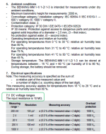
yup that might be part of the problem for sure 🙂 although i could not even find it in the manual 🙁
Benning MM 1-3 Multimeter
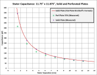
That is it exactly. The ratio of the measured capacitance vs the ideal flat plate capacitance of the same dimensions gives you the efficiency loss from the stator openings. For example, if you measured half the capacitance, you have lost -6dB output. Here are some measurements I made years ago of trends for solid plates vs perforated plates and compared them to theory. Hole size was 1.5mm...so you can see as the airgap spacing approaches the size of the stator holes or slots efficiency loss starts to increase.ill try measure the capacitance ! so if it measures the right value compared to an ideal capacitor of the same dimensions. it should be fine i asume ? and would make it clear if there is enough area driving it 🙂 thats a really simple idea !! thanks bolserst !!
i need to get them appart first to get the DC spacing 🙂 also i cant actually see the true DC spacing. since everything is black. im not sure if the copper is on the inside or the outside. (i asume inside since there is a solder point for the stator connection on the inside)

As you noted, some efficiency loss may also be coming from the location of the conduction layer. You can determine which side of the stator it is on by measuring capacitance of the removable stator spaced away from a piece of sheet metal. Flip the stator keeping spacing to the metal sheet the same. You will measure the highest capacitance when the conducting layer is closest to the metal sheet. Usually if the stator is made of material having high dielectric constant, the efficiency loss is small (<1dB) even with the conduction layer on the outside.
Looks to be the standard 10Meg.yup that might be part of the problem for sure 🙂 although i could not even find it in the manual 🙁
Benning MM 1-3 Multimeter
Nice meter 🙂 supposed to be able to measure capacitance down to 1pF.

OOoh i read over it 🙁 hehe well i dont have expensive equipment, but i thought 120 euro should give me a sort of decent meter without going chinese or fluke on the other side of the spectrum hahaNice meter 🙂 supposed to be able to measure capacitance down to 1pF.
nice explaination and graph about the holes and dc spacing ! pretty cool you can measure it like this without even having to open them up as long as you know the DC spacing !
- Home
- Loudspeakers
- Planars & Exotics
- How high resistor values for voltage divider, to measure Bias of ESL