Hi, my post was in response to your Lol at my 'not difficult'.@mark100
I never said it was impossible, read my post above.
Also, does this still hold up above 35 degrees?
I simply wanted to show how easy it is to see nulls on a unity/synergy with good xovers.
And I believe seeing nulls with a polarity reversal should be easy for any good acoustic design, with good xovers. No?
I hadn't seen your second post..
Let's just say i think the issues you raise with seeing nulls fade away, when a good acoustic design meets up with good xover design.
If I may repeat a previous comment about a single driver section polarity reversal "If you can't hear a difference, it's an indication the xover is not very well phase aligned."
That comment equivalently translates into "if you can't measure a difference, the xover is not very well phase aligned."
(* by phase aligned, I mean having overlaying phase traces throughout xover summation region, which takes care of time alignment too))
And yep, still holds up past 35 degrees. Not as easy to see of course., with more response variations further off-axis.
Here's about 70 degree on-axis.
Line of sight to the CD ceases at 37.5 degrees on the 75 deg conical horn.
And at 70 degrees off, there is no direct line of sight from mic to any of the drivers/ports sections., not even the sub section's port.
Completely around the corner, so to speak.
A combined graph like before got a little hard to follow, given more off axis jaggies, so i split out the polarity inversion graphs.
Light blue in all three graphs, is all sections with normal positive polarity.
First graph, red is HF inverted.
Second, purple, is mid.
Third, green, is low.
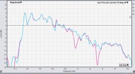
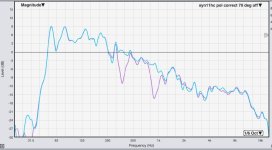
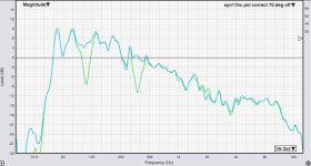
Again, I don't think the null method is a good way to tune. But I do think it makes for a decent smell test for a good crossover.
Phase trace overlay remains by far the best way to fly imo. 🙂
I see minimum and excess phase as simply macro descriptions of phase and time.No, minimum and excess phase components can combine making this method near unusable by visual means alone.
So they are a step away from the specificity of phase and time itself, and lead more to obfuscation than clarity.
Why muck separating out minimum and excess phase, when you can work directly with the real deals.....phase and time.
There's relative phase/timing between frequencies called phase.
There's constant time across all frequencies called time.
There's a relationship between a single source where frequency magnitude response and phase are completely linked together, called minimum phase.
And then there's a relationship between multiple sources producing the same frequencies, where the link between frequency magnitude response and phase gets broken, called excess phase.
That small set is all the definitions I need to know re xovers, in my mind.
Only things needing to be added, is that phase and time cannot be substituted for each other in good xover design.
Nor should the idea of excess phase contain any constant time.
Oh, and even a single driver is almost always multiple sources...cone, surround, diffraction, etc etc. (most of which to ignore)
my 2c
Within the Vituix-CAD-Sixpack you can fortunately use both methods virtually. 😎Again, I don't think the null method is a good way to tune. But I do think it makes for a decent smell test for a good crossover.
Phase trace overlay remains by far the best way to fly imo. 🙂
Many greetings,
Michael
Yes, what an awesome tool (and gift!), V-Cad is for the DIY community.Within the Vituix-CAD-Sixpack you can fortunately use both methods virtually. 😎
If I were into IIR crossovers, I'd take the time to get as proficient with it as possible.
With complementary linear phase xovers though, it's just too easy to get xovers right by going straight to measurements, without any need to simulate.
Why would you do that when the results are totally predictable?it's just too easy to get xovers right by going straight to measurements, without any need to simulate.
Just sitting at your desk/chair/sofa fussing with some settings is a whole lot easier than just having to repeat measurements over and over again.
Unless you're bored and don't mind a tone sweep every few minutes, it's also not very time effective.
In the last 15 years or so, I only had very minor problems that didn't show up in calculating the filters.
A portion from that was also either just human error, or just the lack of or bad measurements (which I also call human error).
That even counts for the more complicated systems.
The only exception are big line arrays (which are super hard to measure to begin with)
Btw, since loudspeakers are minimum phase systems, it's also calculating filters and not simulating them.
The behavior is totally predictable.
I would call finding the right dimensions and system/tuning, simulating.
Although depending how complicated one wants to make things.
Closed/sealed boxes are very predictable as well for example.
But you already have done that before determining the right crossovers.
Of course you can detect such a null by ear compared to a correct phase/frequency response with the right source file (easier with pink noise or sweep as with music).Hi, I’ve heard that if the crossover network is designed properly, reversing polarity of one driver give a deep null at the crossover region on the frequency response. However, what if one does it without measurements, just voicing by ears? Can we detect the deep null by listening? Also, does deep null have any advantages? Are there any designs that are benefit by deep null?
But it's very hard to find the MAXIMUM chancellation by ear! You just notice chancellation but to get perfect addition you must aim for the deepest null possible with your setup. Our ear is good to identify bumps - but not narrow band notches.
Even with a cheap measurement mic it takes a few minutes and 10-20 measurements. That's not a task done by ear to get it perfect.
With complementary linear phase xovers though, it's just too easy to get xovers right by going straight to measurements, without any need to simulate.
I would also like to note that my simulations are based on measurements with timing reference. I have made the experience that such simulations correspond amazingly exactly to what can be measured afterwards.Why would you do that when the results are totally predictable?
Just sitting at your desk/chair/sofa fussing with some settings is a whole lot easier than just having to repeat measurements over and over again.
Unless you're bored and don't mind a tone sweep every few minutes, it's also not very time effective.
Many greetings,
Michael
I dunno, are unity/synergies totally predictable? Or line arrays (like you mentioned), or a dodecahedron, or even simple commercial horn/waveguides over ported or horn loaded cones in trap boxes?Why would you do that when the results are totally predictable?
Just sitting at your desk/chair/sofa fussing with some settings is a whole lot easier than just having to repeat measurements over and over again.
Unless you're bored and don't mind a tone sweep every few minutes, it's also not very time effective.
That's what I've built...other than one flat baffle ring-array attempt.....that was a total turd, and my only failure to date haha. Probably should have simmed it for sure!!! .
Oh, I'm not hung with tone sweeps for making measurements. A dual channel like Smaart can use music with a little inaudible pink thrown in quite well.
Plus, it's continuous allowing temporal averaging and in real time.
Btw, since loudspeakers are minimum phase systems, it's also calculating filters and not simulating them.
The behavior is totally predictable.
I don't consider a loudspeaker to be a minimum phase system. A speaker has regions of behaving as minimum phase, when only one driver section is handing a freq range.
Again, I haven't done any sealed boxes.I would call finding the right dimensions and system/tuning, simulating.
Although depending how complicated one wants to make things.
Closed/sealed boxes are very predictable as well for example.
The way I see it, if I put together a speaker that adheres to known principles of good acoustic design, such as maintaining 1/4 WL c2c or better for example......
and then can dial in xovers for smoothest response and directivity index, guaranteed, in one easy morning via measurements,.....
why not just do that?
Just my style...plus I like the sound and feel of reality more than virtual. (Never heard a sim yet, 🙂 )
And I mean, even if I had simmed the design first to get close, I'm still gonna have to verify it and make adjustments via measurements
I truly think, if folks knew how easy complementary linear phase xovers are to implement....we would probably see a lot more folks skipping the sim stage, especially on conventional two and three way boxes. (moral of the story, ditch IIR xovers, and sims Lol !!!)
That's not a consideration, that is fundamental physics.I don't consider a loudspeaker to be a minimum phase system.
Loudspeakers ARE minimum phase systems.
Obviously to some extend, but you wanna stay extremely far from the region.
For the parts we are interested in, we can simply consider them as minimum phase systems.
Anything that can be measured at least up to about 90 degrees off-axis (ideally more) is just very easy to put in your favorite crossover program and the results will be predictable.
The awkward part about line-arrays, is that they are so enormous and big, that measuring them well, is close to impossible.
The point is that the measurements are reliable, doesn't matter what system you're making.
After that the results will be the same as your put in your calculation software, BECAUSE of the minimum phase behavior.
This is also why it is so important to do your measurements well!!
How a calculated crossover "sounds" comes with experience.
Although if you do your preliminary homework, you already kinda know what to lookout for.
After that it's always a matter of tweaking and tuning, but that is pure subjective.
You can go through a couple of iterations sometimes, although after a while you also know what freq resp curve works and what not.
Doing plenty of research and therefor knowing what to expect before making the system also helps with this.
A good portion of a well performing loudspeaker system is all about the preparation!
But yeah some systems are more predictable than others.
One of the reasons why closed/sealed systems work so well.
They are extremely straightforward, very few variables.
The more parameters and variables you involve, the more difficult it gets also because there will be more errors involved.
I would suggest looking at some stuff from Erin's Audiocorner.
He does a very good job in trying to correlate how things sound and how they measure.
Plus what he personally prefers with that as well.
I don't understand the last point?
The whole point is predicting and than verifying.
But most importantly knowing and understanding the WHY.
By skipping the whole sim/calculation and just turning knobs, you skip the whole WHY part.
Which is one of the most important steps in getting satisfying and consistent end-results.
That's not a consideration, that is fundamental physics.
Loudspeakers ARE minimum phase systems.
Obviously to some extend, but you wanna stay extremely far from the region.
For the parts we are interested in, we can simply consider them as minimum phase systems.
I disagree with your assessment of the fundamental physics.
My assessment is that drivers are minimum phase devices, but the regions of summation between drivers, ie the xover region is not minimum phase.
(as per my post #42.)
The drivers' summation region can easily be minimum phase to a particular point in measured space, and even be considered to be fairly decently min phase across a specific set of polars set.
But try to show me any speaker other than maybe a single full-range driver that is min phase throughout the freq range and throughout space. The unity type builds I like, or truly full range electrostats are the closest I've found.
Maybe I don't communicate well, or you don't read my posts very well....as it appears I'm a lot further down the loudspeaker design and tuning road than you seem to imagine.
Pls take a look at my numerous postings on synergies, and other type build, and measurements in general. Oh, and I've both built home size line arrays & CBTs, as well as been hired to dial in large hanging lines for live sound. ....... fwiw
I think the literature is extremely clear about this.I disagree with your assessment of the fundamental physics.
But believe what you wanna believe.
Personally I don't gain much joy discussing about those things, like theory.
Open a book, read about it, and you will know.
There are plenty of good reads about this stuff.
Besides, that was also not the point btw.
The point was predictability of crossover calculations.
If you find other methods work better for you, that is totally great as well.
Whatever floats your boat.
My only point was that there is no need to do that.
Nothing more, nothing less.
And yeah, there is probably some miscommunication involved, I agree.
I very much agree with you here, about not getting much joy from discussing theory.I think the literature is extremely clear about this.
But believe what you wanna believe.
Personally I don't gain much joy discussing about those things, like theory.
Open a book, read about it, and you will know.
There are plenty of good reads about this stuff.
In fact it drives me half-crazy when folks go off deep into the theory weeds, while evidently not even grasping 101 fundamentals.
I too think the literature is clear on what is and isn't minimum phase...but again, on the side i see it from.
Which is basically, anytime multiple geometric sources are involved, minimum phase response is confined to a spot or region.
Examples:
SynAudCon...."Most electronic components are minimum phase. So are most microphones and single-way loudspeakers. Multi-way loudspeakers rarely are, and rooms never are."
https://www.prosoundtraining.com/2022/09/12/frequency-response-matching-part-2/
B&K has an excellent paper on phase and transient response that discusses how speakers break away from minimum phase. https://www.bksv.com/media/doc/17-198.pdf
Bill Waslo seems to see it the way i do ....https://techtalk.parts-express.com/forum/tech-talk-forum/1290936-explaining-minimum-phase/page2
Anyway, these examples just came from the first page of a quick search using "are loudspeakers minimum phase systems".
Plenty more to easily be found..
And yep, I do have/read some audio books 😉 ...not to mention the many dozens of books and papers saved to disc.

Cool, i'll endeavor to be both clear and polite 🙂And yeah, there is probably some miscommunication involved, I agree.
Yes, great point.I would also like to note that my simulations are based on measurements with timing reference. I have made the experience that such simulations correspond amazingly exactly to what can be measured afterwards.
Many greetings,
Michael
I think establishing a specific timing reference, for all measurements or sims, is a foundational requirement.
And then and only then, can either phase, or drivers' physical offsets, be correctly evaluated.
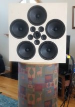
What my eyes see there is a (kind of) 180 Degree synergy/MEH horn... that may or may not have obeyed the 1/4 wave spacing "suggestion" 😉
I like it, thanks for sharing. Have you still got it ? maybe a coax instead of the 6 central drivers ?
What my eyes see there is a (kind of) 180 Degree synergy/MEH horn... that may or may not have obeyed the 1/4 wave spacing "suggestion" 😉
Yep, your eyes see the same things mine do 🙂
I got the idea from some of the "fractal array" builds, and and the image below from one of Tom D's unity/synergy patents.
The dome tweeter/midrange was an SB Acoustics SB26STWGC-4, that i hoped to use down to 650Hz.
Then came the rings of 3" & 10" Faitals.
1/4WL was fairly decent, element to element around each 3" and 10" rings...but of course not close across the rings' diameters
1/4WL was also not too bad going out radially from the center dome , to mids, to lows.
I could get good tuning to a spot, but off-axis plain sucked......no matter what processing was tried....
so I ditched the thing and said never again to multiple drivers handling same freq range, other than with line arrays or unity/synergies.
I came to the conclusion, rightly or wrongly, that the distance across the rings' diameters is a big muck up...
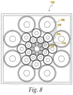
The project did thankfully clarify a couple of concepts though......
I saw that turning the flat surface of ring radiators onto a pyramid surface, naturally closed down the lateral 1/4WL spacing,
especially for c2c distances 'across the ring' so to speak.
And it helped me to more deeply realize what minimum phase is and isn't, like per this thread....
If drivers don't fully couple, ie be within 1/4WL, there is little hope ime for their combined behavior to act as min phase
(other that to a spot or small region)
Yep, I've watched that more than once. Good stuff.
But frankly, and probably just due to my nature, i think he makes it a bit too complicated, to see how phase pragmatically applies...
- Home
- Loudspeakers
- Multi-Way
- How does the sound of “deep null”?
