Joel
So in other words figuring the 20ma on the VR is just for getting it in the correct working area? So it is still capable of working a 40ma load? So it can run two sections of a 5687 at 12ma each without a problem?
Joe
So in other words figuring the 20ma on the VR is just for getting it in the correct working area? So it is still capable of working a 40ma load? So it can run two sections of a 5687 at 12ma each without a problem?
Joe
Thanks Frank for the figures.
Can someone draw me a schematic now?
Head still buzzing still doing the wifes s*it list.
Joe
Can someone draw me a schematic now?
Head still buzzing still doing the wifes s*it list.
Joe
It doesn't "run" them.
you have this...
[B+]---[RESISTOR]---[A]---[0D3]--->Ground
Point "A" is where the plate load resistors of your preamp tube(s) are connected to. In other words, to the plate of the 0D3. The cathode of the 0D3 goes straight to ground.
So, if the draw from A is going to be 24mA from your two tubes combined, we would like the total current through the resistor to be 44mA. 24mA load + 20mA through the VR tube.
The 0D3 wants to always be +150v above ground. So, use a resistor value that will drop the B+ across the resistor down to 150v when there is 44mA across it. If you choose too low a value of resistor, the VR tube will be running at a higher current than 20mA. If you choose too high, it will be running less than 20mA.
Hi,
Either way it's not critical.
All you need to do is provide for around 160VDC for the tube to ionise its gas.
No regulator can ever regulate without having a voltage difference between its input and output.
In this particular case the tube won't be regulating much, it will do what a zener diode does: clamp a voltage, in this case 150VDC.
If you let too much current flow, say close to 40ma or more, the tube won't be able to clamp the voltage anymore since the gas will reach full ionisation.
One major disadvantage here is that you just can't add any reservoir capacitance after the VR tube so you best take care of the psu in front of it.
Still if you like what it does soundwise, it's easy enough to make a regulated B+ where you won't suffer this disadvantage and have a rocksteady B+ for the preamp.
Regulation within a mV is certainly possible but, in my opinion, once you start regulating one part of the equation you'd better regulate all that needs it.
Cheers,😉
If you choose too low a value of resistor, the VR tube will be running at a higher current than 20mA. If you choose too high, it will be running less than 20mA.
Either way it's not critical.
All you need to do is provide for around 160VDC for the tube to ionise its gas.
No regulator can ever regulate without having a voltage difference between its input and output.
In this particular case the tube won't be regulating much, it will do what a zener diode does: clamp a voltage, in this case 150VDC.
If you let too much current flow, say close to 40ma or more, the tube won't be able to clamp the voltage anymore since the gas will reach full ionisation.
One major disadvantage here is that you just can't add any reservoir capacitance after the VR tube so you best take care of the psu in front of it.
Still if you like what it does soundwise, it's easy enough to make a regulated B+ where you won't suffer this disadvantage and have a rocksteady B+ for the preamp.
Regulation within a mV is certainly possible but, in my opinion, once you start regulating one part of the equation you'd better regulate all that needs it.
Cheers,😉
Looks good Bas, although it's more of a series type regulator circuit isn't it, due to the CCS rather than solely a shunt?
Hi Joel,
As far as I understand it it is still a shunt type regulator. The CCS does just that...delivers constant current (Like a fancy resistor or choke) No voltage regulation at all. This is left to the VR tubes.
I just set the CCS to about 20mA more than the circuit needs and then the VR's ignite.
The Cascoded CCS is supposed to be like a brick wall filter. Like a 40 000H choke or something. Funny thing is....you still hear changes when fiddling with the stages that are in front of the CCS. Quite baffling.....??!!??!!

Cheers,
Bas
Hi,
It's a shunt allright.
Have you considered moving the CCS downstream and set its' current output to what the circuit needs?
Normally, you shouldn't.
If you feel like giving it a try let us know the results, please.
Next step up would be to use a real voltage regulator with the CCS.
Cheers,😉
As far as I understand it it is still a shunt type regulator.
It's a shunt allright.
I just set the CCS to about 20mA more than the circuit needs and then the VR's ignite.
Have you considered moving the CCS downstream and set its' current output to what the circuit needs?
Funny thing is....you still hear changes when fiddling with the stages that are in front of the CCS. Quite baffling.....??!!??!!
Normally, you shouldn't.
If you feel like giving it a try let us know the results, please.
Next step up would be to use a real voltage regulator with the CCS.
Cheers,😉
Bas and Frank,
The CCS in Bas' PSU is before the VR tube, not before the resistor - so how do you figure that it's not doing any series voltage regulation?
The current demand from the CCS (not the VR tube) is setting the voltage drop across that resistor. In fact, the VR tube in this circuit is only serving to lower the PSU output impedance - not regulating the voltage really.
Gentle-beings
Draw the pictures, do the math.
First: what is the raw supply output voltage??? This is a choke-input filter but it is very lightly loaded. At less than 5mA load, it isn't choked any more, but approaches a cap-in filter and the voltage soars. It appears that Joe did do the homework and got the input choke big enough for a load of about this size. Duncan's calc gives these approximate voltages:
250VDC at 12mA
215VDC at 52mA
THis depends on the wall-power voltage, so we should allow a lot of variance. Maybe 275 one day, 200 another day.
I have assumed silicon rectifiers. If you use hollow rectifiers the voltage will be much lower.
Now: the 0D3 will die if you let it suck more than 40mA, and it is useless if you don't let it have 5mA. Joe says his 5687 amp needs 12mA, but tubes vary so I'll say it could be as little as 10mA or as much as 15mA.
The worst case for the 0D3 is: high line voltage, 5687 out of socket (stuff happens). Then the resistor marked "?" could have 275V one side, 150V on the other side, and must not pass more than 40mA. (275-150)/0.040= 3125Ω minimum resistance at "?" to ensure the 0D3 will not have a bad day.
At the other extreme: we could say the 0D3 must maintain 5mA when the 5687 tube is in-socket, we have a 15mA 5687, wall voltage is low. Now the resistor at "?" has 215V (probably not that low) one side, 150V (or perhaps 148V) on the other, and must pass 5mA=15mA= 20mA. (215-148)/0.20= 3350Ω maximum resistance.
This thing barely works over all likely cases. The "?" resistor must be between 3,125 and 3,350Ω, which doesn't leave any tolerance. I'm not too worried, because you may not have high-line the same day you leave the 5687 out, and if the "150V" sags a bit on low-line days the 5687 won't complain.
But the only value that keeps the 5687 at 148-150V and does not allow death of the 0D3 is 3,300Ω.
Normally you feed a gas-regulator with at least twice the design output, to allow for line and load variations. So we could start with 300VDC or even the 430VDC of those same parts arranged as capacitor-input.
It is probably not necessary to use a LCLC filter: the 0D3 is pretty good about wiping off the ripple.
> decouple the tube using a 0.100uF filmcap (max) to prevent the tube from oscillating.
Right, a gas-tube with a capacitor will oscillate. But a gas-tube without a cap is a powerful noise (hiss) source. So the 0D3 has been gimmicked so it will stand 0.1µFd without oscillating, and you will probably need a 0.1µFd so you don't get large noise in the plate of the 5687.
Of course this scheme would work just as well with a larger plate resistor on the 5687 fed from the 250V directly. Or an RC decoupling network to give a little more filtering and just-enough voltage drop (try 5K and 100µFd). Regulated voltage is not terribly important in tube audio (though it can be the final polish on a good design). Regulation can be handy if the only available supply is much more than you need. But gas-tube regulators are really noisy beasts, and were expensive in their day, so hardly anybody used them. (One place I know: in broadcast and recording gain limiters, the VCA was fed regulated voltage so that the threshold level didn't change when the utility power varied.)
And the glow is cool.
Draw the pictures, do the math.
An externally hosted image should be here but it was not working when we last tested it.
First: what is the raw supply output voltage??? This is a choke-input filter but it is very lightly loaded. At less than 5mA load, it isn't choked any more, but approaches a cap-in filter and the voltage soars. It appears that Joe did do the homework and got the input choke big enough for a load of about this size. Duncan's calc gives these approximate voltages:
250VDC at 12mA
215VDC at 52mA
THis depends on the wall-power voltage, so we should allow a lot of variance. Maybe 275 one day, 200 another day.
I have assumed silicon rectifiers. If you use hollow rectifiers the voltage will be much lower.
Now: the 0D3 will die if you let it suck more than 40mA, and it is useless if you don't let it have 5mA. Joe says his 5687 amp needs 12mA, but tubes vary so I'll say it could be as little as 10mA or as much as 15mA.
The worst case for the 0D3 is: high line voltage, 5687 out of socket (stuff happens). Then the resistor marked "?" could have 275V one side, 150V on the other side, and must not pass more than 40mA. (275-150)/0.040= 3125Ω minimum resistance at "?" to ensure the 0D3 will not have a bad day.
At the other extreme: we could say the 0D3 must maintain 5mA when the 5687 tube is in-socket, we have a 15mA 5687, wall voltage is low. Now the resistor at "?" has 215V (probably not that low) one side, 150V (or perhaps 148V) on the other, and must pass 5mA=15mA= 20mA. (215-148)/0.20= 3350Ω maximum resistance.
This thing barely works over all likely cases. The "?" resistor must be between 3,125 and 3,350Ω, which doesn't leave any tolerance. I'm not too worried, because you may not have high-line the same day you leave the 5687 out, and if the "150V" sags a bit on low-line days the 5687 won't complain.
But the only value that keeps the 5687 at 148-150V and does not allow death of the 0D3 is 3,300Ω.
Normally you feed a gas-regulator with at least twice the design output, to allow for line and load variations. So we could start with 300VDC or even the 430VDC of those same parts arranged as capacitor-input.
It is probably not necessary to use a LCLC filter: the 0D3 is pretty good about wiping off the ripple.
> decouple the tube using a 0.100uF filmcap (max) to prevent the tube from oscillating.
Right, a gas-tube with a capacitor will oscillate. But a gas-tube without a cap is a powerful noise (hiss) source. So the 0D3 has been gimmicked so it will stand 0.1µFd without oscillating, and you will probably need a 0.1µFd so you don't get large noise in the plate of the 5687.
Of course this scheme would work just as well with a larger plate resistor on the 5687 fed from the 250V directly. Or an RC decoupling network to give a little more filtering and just-enough voltage drop (try 5K and 100µFd). Regulated voltage is not terribly important in tube audio (though it can be the final polish on a good design). Regulation can be handy if the only available supply is much more than you need. But gas-tube regulators are really noisy beasts, and were expensive in their day, so hardly anybody used them. (One place I know: in broadcast and recording gain limiters, the VCA was fed regulated voltage so that the threshold level didn't change when the utility power varied.)
And the glow is cool.
Joel said:Bas and Frank,
The CCS in Bas' PSU is before the VR tube, not before the resistor - so how do you figure that it's not doing any series voltage regulation?
The current demand from the CCS (not the VR tube) is setting the voltage drop across that resistor. In fact, the VR tube in this circuit is only serving to lower the PSU output impedance - not regulating the voltage really.
Then let's say you replaced the VR tube with a resistor of say, 150/.02 = 7500 ohms, and put a reasonable capacitor across it. It has a low dynamic resistance, correct? But is it regulated?
It looks to me like you're just trying to disagree with Frank because you hate him. Even going against electrical logic to do it.
Tim
Thanks to all that have contributed to VR 101 the care and feeding of the 0D3. Thanks for the schematic, the only thing missing is my 6X4 full wave rectifier. I can hardly wait for the rest of my parts to arrive this week so construction can begin.
Watch for the glow
Joe
Watch for the glow
Joe
Hi,
Horses for courses, as usual.
Glad to see you know your stuff even though I'm not in total agreement with your conclusions:
Well, I feel it is. To me at least it provides for ultimate performance, granted you have to know what you're doing or want to achieve, but once correctly implemented it really can be an ear-opener.
Granted, there are several routes one can travel and I'd be the last person to make sweeping generalisations on anything as broad as this topic...still, in general I'm not against a well designed PSU.
Most zeners are even worse because of their awful tempco.
As said 0.100uF is really a lot already, a few tens of nanoF will often be more than adequate.
Nowadays I feel that once again we should consider isolating our audio gear from the vagaries of the mains...I never thought that looking at what the most demanding guys were doing and implementing it in more downstream applications would hurt us in any way.
Thank you for your contibution PRR,😉
Regulated voltage is not terribly important in tube audio (though it can be the final polish on a good design).
Horses for courses, as usual.
Glad to see you know your stuff even though I'm not in total agreement with your conclusions:
Regulated voltage is not terribly important in tube audio (though it can be the final polish on a good design).
Well, I feel it is. To me at least it provides for ultimate performance, granted you have to know what you're doing or want to achieve, but once correctly implemented it really can be an ear-opener.
Granted, there are several routes one can travel and I'd be the last person to make sweeping generalisations on anything as broad as this topic...still, in general I'm not against a well designed PSU.
But a gas-tube without a cap is a powerful noise (hiss) source
Most zeners are even worse because of their awful tempco.
As said 0.100uF is really a lot already, a few tens of nanoF will often be more than adequate.
One place I know: in broadcast and recording gain limiters, the VCA was fed regulated voltage so that the threshold level didn't change when the utility power varied.)
Nowadays I feel that once again we should consider isolating our audio gear from the vagaries of the mains...I never thought that looking at what the most demanding guys were doing and implementing it in more downstream applications would hurt us in any way.
Thank you for your contibution PRR,😉
PRR said:...But a gas-tube without a cap is a powerful noise (hiss) source....
Regulated voltage is not terribly important in tube audio (though it can be the final polish on a good design). Regulation can be handy if the only available supply is much more than you need. But gas-tube regulators are really noisy beasts, and were expensive in their day, so hardly anybody used them.
Hi PRR,
I disagree with your post.
a) As I said, I have just built an audio amplifier utilizing gas tubes to decouple both the preamp and power stages. They are not bypassed, and scope readings show no noise whatsoever.
b) A VR tube can handle over 100mA at startup, so a brief foray above 40mA will not "kill" them.
c) Regulated voltage is as important in an audio amp as in any other application if you care to reduce distortion to the lowest possible level without the use of NFB.
d) They probably used to be expensive, but now they are dirt cheap and can attenuate ripple quite well. I know of no cap and choke combination that costs $2
Joel
Tim,
Give me an ounce of credit please, and let's keep this on a technical level, rather than a personal one.
Look again at Bas' schematic. Now tell me, how much current the VR tubes can pull through the CCS?
Give me an ounce of credit please, and let's keep this on a technical level, rather than a personal one.
Look again at Bas' schematic. Now tell me, how much current the VR tubes can pull through the CCS?
Joel said:
Hi PRR,
I disagree with your post.
a) As I said, I have just built an audio amplifier utilizing gas tubes to decouple both the preamp and power stages. They are not bypassed, and scope readings show no noise whatsoever.
b) A VR tube can handle over 100mA at startup, so a brief foray above 40mA will not "kill" them.
c) Regulated voltage is as important in an audio amp as in any other application if you care to reduce distortion to the lowest possible level without the use of NFB.
d) They probably used to be expensive, but now they are dirt cheap and can attenuate ripple quite well. I know of no cap and choke combination that costs $2
Joel
Hi
a) Most scope have limitted sensitivity. If 1 mV is no noise, and considered "low", depends on the circuit and requirements
b) OK
c) Such a statement cannot be made without giving the requirements and clarifying which circuit is used
d) Agreed. What about the sound quality of that combo ?
best regards
Hi,
Probably not...try some 47nF.
Oh, don't expect too much regulation from a VR tube.
They're essentially the same as zener diodes, namely voltage references... not voltage regs.
Cheers,😉
I have some 330pf caps to go from B+ to ground. Will these be big enough?
Probably not...try some 47nF.
Oh, don't expect too much regulation from a VR tube.
They're essentially the same as zener diodes, namely voltage references... not voltage regs.
Cheers,😉
can't get 0D3 to stay on, any ideas?
Ok, I finally have gotten around to playing with my latest project line amp. Its a 5687 with a power supply consisting of these parts. A Hammond 272BX transformer, 6X4 rectifier tube, (2) Hammond 157G 30H
40Ma DC chokes, a dual 50mfd capacitor, and a 0D3 voltage regulator tube.
The power supply voltage after the last cap is 434volts. This is without the 0D3 or the 5687 tube. When I plug in the 0D3 tube it lights up ok without the load(5687 tube). When I put the 5687 tube into the circuit the 0D3 lights for a split second then goes out.
I have tried a 0B3(VR90) tube and I can put the 5687 tube in circuit and I end up with 93.9 volts at the output of the tube.
I have also tried a 0A3 tube and it puts out 80.6 volts with the 5687 tube in circuit.
What the heck am I doing wrong that the 0D3 tube won't run the load?
Any help here would be appreciated very much.
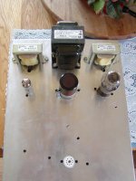
I will throw in an unfinished picture of the animal. Keep in mind that this is a garage animal so cost and finish are minimal.
Ok, I finally have gotten around to playing with my latest project line amp. Its a 5687 with a power supply consisting of these parts. A Hammond 272BX transformer, 6X4 rectifier tube, (2) Hammond 157G 30H
40Ma DC chokes, a dual 50mfd capacitor, and a 0D3 voltage regulator tube.
The power supply voltage after the last cap is 434volts. This is without the 0D3 or the 5687 tube. When I plug in the 0D3 tube it lights up ok without the load(5687 tube). When I put the 5687 tube into the circuit the 0D3 lights for a split second then goes out.
I have tried a 0B3(VR90) tube and I can put the 5687 tube in circuit and I end up with 93.9 volts at the output of the tube.
I have also tried a 0A3 tube and it puts out 80.6 volts with the 5687 tube in circuit.
What the heck am I doing wrong that the 0D3 tube won't run the load?
Any help here would be appreciated very much.
I will throw in an unfinished picture of the animal. Keep in mind that this is a garage animal so cost and finish are minimal.
Attachments

Looks fine to me. 🙂
What is the design current draw of the 5687, and what is the dropping resistor for the regulator?
Tim
What is the design current draw of the 5687, and what is the dropping resistor for the regulator?
Tim
- Home
- Amplifiers
- Tubes / Valves
- How do you use a 0D3 regulator?