trying to get the overall response as flat as possible
That's not what I prefer and what sounds natural to me.
If your mid/high drivers have wide dispersion you'll get too much mid/highs at your listening position because of the room reflections.
Take a look how I designed my speakers.
Lots of information can be found on the site of Troels, none of his designs have a flat frequency response.
Regards,
Danny
There are a lot of well-established goals, none of which people agree on! But the worst case is a design that has "horns" in the frequency response at off axis angles, coming from the different polar patterns of the lower and upper driver. It's a subject that can fill books and it already has! The important thing is to make an informed decision on what your polar pattern should look like, then design and measure toward that goal. A "layman's guess" will not turn out happy. I haven't gone through sreten's list, but I'd certainly start by reading Floyd Toole and Sean Olive's various papers and presentations on the subjective effects of varying polar patterns.
One more thing I should have mentioned but didn't- large signal behavior at crossover. Many of the steps that it takes to get rid of off-axis anomalies will seriously compromise power handling and distortion at crossover.
No, you did not choose an easy project. 😀
Update:
The measurement microphone has arrived and I've been using ARTA to run a few basic FR tests, this lead to a re-designed crossover. (and of course a better understanding of xo design)
Also, I confirmed my suspicion that the mid-range unit is the same as used in the normal 2-way XT-2 speakers. Given that I only have 2 bass woofers, it seemed logical to switch to a 2.5 way topology.
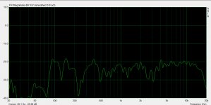
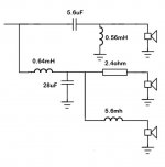
I've attached pictures of the old and new crossovers, which should give a good idea of what's going on, and a FR sweep of the speaker, I'm not too worried about the low end response atm as the cabinet is floor standing with half the front missing whilst I tune the crossovers.
The measurement microphone has arrived and I've been using ARTA to run a few basic FR tests, this lead to a re-designed crossover. (and of course a better understanding of xo design)
Also, I confirmed my suspicion that the mid-range unit is the same as used in the normal 2-way XT-2 speakers. Given that I only have 2 bass woofers, it seemed logical to switch to a 2.5 way topology.
I've attached pictures of the old and new crossovers, which should give a good idea of what's going on, and a FR sweep of the speaker, I'm not too worried about the low end response atm as the cabinet is floor standing with half the front missing whilst I tune the crossovers.
Attachments

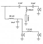
update again.. i was sure i should be able to do better so i spent more time and tightened up the tweeters FR, ended up with a very steep roll off at about 1.7k, (give or take, that's from memory!) and flat (ish) response from there up. The new crossover design is attached, with this crossover the speaker is really singing, just a few questions:
1.The overall tweeter output is much lower than if I just had a high value cap in series, is this normal, and is there a way to regain some output?
2. Is the need for the resistor in line with the parallel inductor on the tweeter network a sign that I've spec'd the value wrong, or is this normal to come across?
Also, the bass driver is much lower efficiency than the mid, which means the mid ends up doing too much bass work and overpowering the rest of the drivers. With the current design this isn't too bad - in fact, I may just order some more resistors and attenuate the mid individually, but if there's another way to help the mid to play ball I'm open to suggestions!
Also... port tuning. This is in a ported enclosure, can I tune the port length with the aid of the measurement mic (maybe measuring internal FR and port FR?) or do I need to learn to do some proper calculations to get the best out of this enclosure? (there is a port in the enclosure already, made form some 50mm drain pipe I had laying around)
As soon as I find my camera I'll post actual pictures of the speakers!
Sorry it's taken so long top get on this, I'm sure all the forum members that have been engineering students will sympathize!
Attachments
Last edited:
Wow, that's two very negative responses now.
Is there some taboo about getting into DIY? Are you wishing me not to bother?
I made it clear that I am learning, studying, and that it is in my nature to design and develop new solutions. It is not in my nature to take anothers work and call it my own, however I am happy to learn from it.
Please, if you have nothing positive to say, get afk.
Audio forums are full of hate full people, especially if you are into experimenting and tweaking. Kick back, kick hard. They're hyenas, thriving on people being stuck.
When you use formulas for woofers and some mid drivers, their inductance is as big or bigger than the resistance at the crossover point. You can tame the ringing, harsh result by adding a resistor in series with the capacitor, 2 ohm typically. Avoid a traditional Zobel.
You can take time-gated measurements in ARTA that will be much more helpful.
1. With ARTA all set up and functioning (also make sure you've loaded your mic calibration if you have a calibrated mic), click over to impulse mode ("IMP" button upper-left"), and click the red arrow to record, which pops up the record box.
2. Click the MLS tab (it's a fast type of measurement, good for when you're experimenting). If all the settings look right (you can stay with the default signal length), click "Generate MLS" to start the signal going, adjust volume to sound close to how loud you might listen, and then adjust mic level to get a strong signal bar that isn't banging into the 0dB level. Then, click the "Record" button.
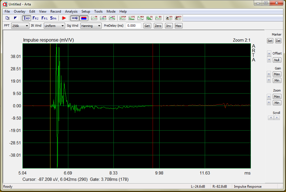
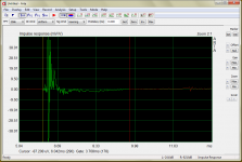
3. Now you've got an impulse, if all went well. Mess with the gain, zoom, and scroll until you can see it well (example below). If you're lucky, your first major reflection will be far enough away that you can see it. In my example, that is the red blip off to the right side. If not, it will be mixed up with the main impulse, but you'll be able to figure that out with some messing around.
4. With the cursor over the graph, click and hold the left mouse button, and drag the yellow line that appears to the start of your impulse, like in the example. Let go, and then click and hold the right mouse button. This gives you a red line. Drag that out to where the graph appears to be settling to zero, but before it increases in amplitude again. If you need a guess, drag it out until the "Gate: ___ms (###)" line at the bottom is around 4ms. The part between these two lines is now your gated measurement window.
4. Click the first graph button at the top ("FR") to generate smoothed frequency response. Now a new window pops up with the response of your measurement. You will notice a yellow line at the bottom, and left of this line (and a bit right of it too), your response will be falsely smoothed and rolled off. That is the low frequency part that is invalidated by the gating, and that is fine. If you get strange ripples, there is probably a reflection. You can close the window, right-click to move your red gate line to an earlier point in time, and then go back to the FR and see what happened. You can also save overlays in the FR window to see what things look with at different gate times.
From the FR window, you can also export frd files to use for crossover simulation, but I'm not getting into that in this post 🙂.
1. With ARTA all set up and functioning (also make sure you've loaded your mic calibration if you have a calibrated mic), click over to impulse mode ("IMP" button upper-left"), and click the red arrow to record, which pops up the record box.
2. Click the MLS tab (it's a fast type of measurement, good for when you're experimenting). If all the settings look right (you can stay with the default signal length), click "Generate MLS" to start the signal going, adjust volume to sound close to how loud you might listen, and then adjust mic level to get a strong signal bar that isn't banging into the 0dB level. Then, click the "Record" button.
3. Now you've got an impulse, if all went well. Mess with the gain, zoom, and scroll until you can see it well (example below). If you're lucky, your first major reflection will be far enough away that you can see it. In my example, that is the red blip off to the right side. If not, it will be mixed up with the main impulse, but you'll be able to figure that out with some messing around.
4. With the cursor over the graph, click and hold the left mouse button, and drag the yellow line that appears to the start of your impulse, like in the example. Let go, and then click and hold the right mouse button. This gives you a red line. Drag that out to where the graph appears to be settling to zero, but before it increases in amplitude again. If you need a guess, drag it out until the "Gate: ___ms (###)" line at the bottom is around 4ms. The part between these two lines is now your gated measurement window.
4. Click the first graph button at the top ("FR") to generate smoothed frequency response. Now a new window pops up with the response of your measurement. You will notice a yellow line at the bottom, and left of this line (and a bit right of it too), your response will be falsely smoothed and rolled off. That is the low frequency part that is invalidated by the gating, and that is fine. If you get strange ripples, there is probably a reflection. You can close the window, right-click to move your red gate line to an earlier point in time, and then go back to the FR and see what happened. You can also save overlays in the FR window to see what things look with at different gate times.
From the FR window, you can also export frd files to use for crossover simulation, but I'm not getting into that in this post 🙂.
Attachments
You should simulate the bass enclosure with WinISD or one of the other thousands of bass simulators. BUT, you can see the tuning freq. of the port with your mic. The easiest way is actually to measure to woofer from very close (1cm, say). You should see a deep notch in the response at the port frequency.Also... port tuning. This is in a ported enclosure, can I tune the port length with the aid of the measurement mic (maybe measuring internal FR and port FR?) or do I need to learn to do some proper calculations to get the best out of this enclosure? (there is a port in the enclosure already, made form some 50mm drain pipe I had laying around)
OK, there's a degree of truth to this but effective measurement is no easy task. I used to believe this more as I was improving my measurement skills. I notice you asked about this before on another thread. The better you measure the better the results will be.The more you build speakers, the more you may rely on your ears. Measurement tools can only give you average result. You need your experienced ears to go beyond that.
If you design a polar response before you build you'll know roughly what to expect from the result, and it can produce a very good starting point. Not all speakers can be made great though, you need to design the faults out before you cross.
It can take several dozen response plots to obtain a power response baseline from an assymetrical tweeter, although it may be done with just a couple of dozen once the process is understood...then you'll need considerable processing to extract the data which you'll probably have to do yourself.
You'll at least need a listening axis response phase plot although proper combining through the crossover region to confirm power through the crossover region might require several phase plots, considerable calculation (and possible further design).
I'm a little surprised nobody has had any direct observations or advice on the crossover design, either old or new. Any 'try this' would be great 😉
Also, the parallel inductor on the tweeter was creating a spike in the FR, any ideas why on this? (the resistor removes the spike and helps create a flat-then-steep filter) It would be good to improve my intuition on that.
My arta response measurements are a little all over the place, but they are reliably so, is this just room interaction preventing a flat(ish) response? the overall sound of the speaker is certainly improving, and without having a stereo pair it's a little hard to tell how good it actually is (for me a lot of the enjoyability of a 'great' speaker is the imaging)
Dumptruck - all of this post is priceless, thank you (obviously I'm new to ARTA so any help I can get is great)
Not sure I am completely following you, I'll give you my 'nanoob' interpretation... my understanding is that, byond trying to achieve smooth roll-off of FR across a wide range of angles, phase issues through the crossover network will effect output level at crossover frequency and I need to ensure it is done correctly, is that right?
One last note: I tried these at low volume levels with simple first order xo's lastnight, expecting them to sound worse, though they were arguably better, is this due to the low listening levels or something else? (I'm guessing all the advantages of using 2nd/3rd order slopes on the xo kick in at a reasonable volume)
Also, the parallel inductor on the tweeter was creating a spike in the FR, any ideas why on this? (the resistor removes the spike and helps create a flat-then-steep filter) It would be good to improve my intuition on that.
My arta response measurements are a little all over the place, but they are reliably so, is this just room interaction preventing a flat(ish) response? the overall sound of the speaker is certainly improving, and without having a stereo pair it's a little hard to tell how good it actually is (for me a lot of the enjoyability of a 'great' speaker is the imaging)
You can take time-gated measurements in ARTA that will be much more helpful.
Dumptruck - all of this post is priceless, thank you (obviously I'm new to ARTA so any help I can get is great)
If you design a polar response before you build you'll know roughly what to expect from the result...
You'll at least need a listening axis response phase plot although proper combining through the crossover region to confirm power through the crossover region might require several phase plots, considerable calculation (and possible further design).
Not sure I am completely following you, I'll give you my 'nanoob' interpretation... my understanding is that, byond trying to achieve smooth roll-off of FR across a wide range of angles, phase issues through the crossover network will effect output level at crossover frequency and I need to ensure it is done correctly, is that right?
One last note: I tried these at low volume levels with simple first order xo's lastnight, expecting them to sound worse, though they were arguably better, is this due to the low listening levels or something else? (I'm guessing all the advantages of using 2nd/3rd order slopes on the xo kick in at a reasonable volume)
I'm a little surprised nobody has had any direct observations or advice on the crossover design, either old or new.
Well, it would help to have impedance measurements, target functions, and actual transfer characteristics. For SPL, you absolutely need raw driver responses (on baffles) and polar pattern. A single on-axis measurement tells you very little.
Did you get the d'Appolito book I recommended? Dickason's Louspeaker Cookbook would also be of great help here. Like I said, you picked a very difficult first project, so expect to have to work hard at it rather than delegate the design. 😀
IMy arta response measurements are a little all over the place, but they are reliably so, is this just room interaction preventing a flat(ish) response?
As a previous poster mentioned, you need to take gated impulse measurements with ARTA when doing crossover design. Here is a tutorial I wrote on how to do that:
Making gated-impulse frequency measurements using ARTA
This gets you the frequency response above about 250Hz. Lower than that and you need to take nearfield measurements and splice them together with the gated impulse measurement.
-Charlie
Thanks to all for the encouragement and advice, it's really appreciated.
I've started taking measurements today of driver impedance, and they're quite far off what is printed on the stickers which says 8ohm.
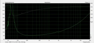
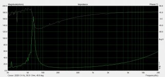
Both the tweeter and the mid range seem to have a nominal impedance of about 4 ohms, whilst the bass woofer has an impedance of about 8. Fo appears to be around 850Hz, 90Hz and 65Hz respectively. The phase plot for the bass woofer looks nuts to me but maybe this is normal (pictures will follow this evening I promise!)
With this in mind, it seems I would struggle to get the bass driver's output to match the mid and tweeter without putting a large L-Pad on the pair (for the proposed 2.5 way design) - a problem I was already having.
Would anybody agree that I would be better off purchasing another bass driver, so that I have two per side (as per the original design) in which case the impedance and hopefully output of the drivers would match more naturally? (obv. then I'd expect to switch back to 3-way)
or... is it too early to tell, and should a wait till I have chance to take the on-baffle axis response FR sweep measurements?
I've started taking measurements today of driver impedance, and they're quite far off what is printed on the stickers which says 8ohm.
Both the tweeter and the mid range seem to have a nominal impedance of about 4 ohms, whilst the bass woofer has an impedance of about 8. Fo appears to be around 850Hz, 90Hz and 65Hz respectively. The phase plot for the bass woofer looks nuts to me but maybe this is normal (pictures will follow this evening I promise!)
With this in mind, it seems I would struggle to get the bass driver's output to match the mid and tweeter without putting a large L-Pad on the pair (for the proposed 2.5 way design) - a problem I was already having.
Would anybody agree that I would be better off purchasing another bass driver, so that I have two per side (as per the original design) in which case the impedance and hopefully output of the drivers would match more naturally? (obv. then I'd expect to switch back to 3-way)
or... is it too early to tell, and should a wait till I have chance to take the on-baffle axis response FR sweep measurements?
Yes. Impedance does not tell you what the sensitivity is.or... is it too early to tell, and should a wait till I have chance to take the on-baffle axis response FR sweep measurements?
Yes. Impedance does not tell you what the sensitivity is.
Yeah, don't know if I said in a previous post that the woofer has much lower sensitivity than the mid/tweeter units, obviously they were meant to be used in parallel in the original 3-way design 🙁 (I only have 3 bass woofers atm)
The impedance plots are attached.
With a ported design, are you dealing with box internal air resonance and port resonance in two separate calculations? or is the box tuned by the port length?
(I know that's probably a stupid question, but it's one I'm finding hard to get an answer to!)
Attachments

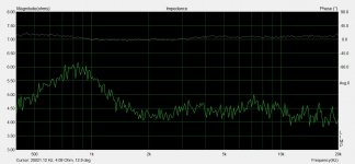
Are you using a jig cable with an amplifier in the loop or just line level? The noise makes me think line level. In any case...
- did you measure impedance of some low value resistors to make sure you're getting accurate magnitude?
- are you doing lots of averages and still getting that much noise?
- are these measurements in the enclosure? what's it like? Either the mid is ported, or that big spike at 90Hz is a severe resonance or measurement problem.
- The phase for the bass woofer is normal for a sealed box - it wraps at Fc where the impedance peak is.
Are you using a jig cable with an amplifier in the loop or just line level? The noise makes me think line level. In any case...
- did you measure impedance of some low value resistors to make sure you're getting accurate magnitude?
- are you doing lots of averages and still getting that much noise?
- are these measurements in the enclosure? what's it like? Either the mid is ported, or that big spike at 90Hz is a severe resonance or measurement problem.
- The phase for the bass woofer is normal for a sealed box - it wraps at Fc where the impedance peak is.
I used line level with a 470ohm resistor.
- I didn't measure the impedance of a low value resistor, but I will do
- I tried multiple measurements but they all came out pretty much the same, I attempted to remove the noise 'by eye' but that lead to the obvious '2nd spike'
- the measurements were with raw drivers sitting on my kitchen table
- as above
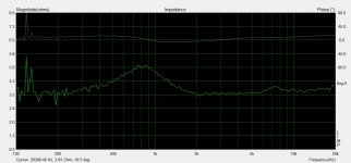
Oh, it's normal for free air too, but I'm a little surprised Fs is so high (but, I know nothing about these speakers). Are you using stepped sine signal in LIMP? Use the pink PN with linear averaging.
yeah I was using stepped sine, i'll go and try noise now.
.....I presume I need all 100 measurements to get a decent average?
.....I presume I need all 100 measurements to get a decent average?
Last edited:
You'll be able to see when it stops getting better. IIRC, it's usually pretty much done by 15 averages for me.
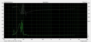
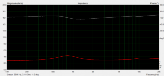
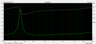
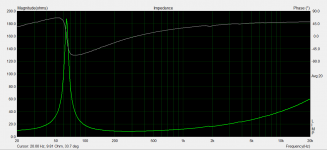
Well... that wasn't what I was expecting to learn today but none-the-less, here's some much better graphs 😱
My 2.4 ohm resistors measure as 2.525 however (unfortunately I measured these after the drivers, so I guess we just multiply the chart resistance values by 0.95 to get correct values?)
My 2.4 ohm resistors measure as 2.525 however (unfortunately I measured these after the drivers, so I guess we just multiply the chart resistance values by 0.95 to get correct values?)
Attachments
- Status
- Not open for further replies.
- Home
- Loudspeakers
- Multi-Way
- How do you finalize/tweak your design when it's 'half built' (noob help please)