You do see that effect yes, but for a simple CCS with a simple voltage reference (e.g. LED) it is quite minimal.I'm not sure about this, self heating might mess up the output impedance for very low frequencies: high VCE -> high Pd -> high junction temperature -> lower VBE -> slightly higher current.
The self-heating effect can be calculated.
Let's suppose we have a TO-92 transistor (200°C/W), at 5mA.
Delta Vce = 1V
=> Delta Pd = 5mW
=> Delta Tj = 1°C
=> Delta Vbe = 2mV
Now, if it is biased by a LED, it will have something like 1.1V on a 220R resistor.
=> Delta I = 10µA
=> Output impedance = DeltaV/DeltaI = 100kOhm
It is not much below the impedance resulting from Early effect. So impedance will go down a little at low frequencies. The corner frequency depends on device thermal inertia, which is usually not specified.
Increasing the bias voltage (more LEDs and a larger resistor) will reduce both effects.
For a CCS with a higher current, having a low drop in the resistor reduces wasted power so it is nice. But this increases Early effect and self heating... so while it is easy to get relatively high impedance (like 100k+) with a single transistor, a resistor and a LED, if you need a couple hundred mA or more, and you don't want too much drop voltage, it gets more complicated.
Cascoding it will also reduce both effects. For the same voltage drop, cascoding is much better than increasing the bias, but needs extra parts. Once cascoded, most of the error comes from the cascode base current (which also depends on its temperature).
Going one step further is to put a darlington as a cascode. This lowers the base current error from the cascode so it gets better at LF. It also gets better at HF if the cascode is a power transistor (high capacitance) and the darlington a low capacitance one.
I had to do all this cause I needed a high current (several amps) CCS with a low drop (a few volts). Self heating on this one starts to lower the impedance below a few hundred Hz. It still manages a few mOhms at the top, a few hundred k's at LF, and a few pF capacitance... the darlington really is the trick.
If you can drop 200V like Gary Pimm it's another story.
Last edited:
Yes, the small signal parameter you want is the derivative at the operating point.
That's the Early voltage Va. If you extend the Ic/Vce characteristic backwards, till you cross the x-axis to the left, negative side, that cross point is Va.
Jan
That's the Early voltage Va. If you extend the Ic/Vce characteristic backwards,
till you cross the x-axis to the left, negative side, that cross point is Va. Jan
Yes, Va (plus Vcollector, which is small by comparison) divided by Ic is the output resistance.
It's a graphical way of estimating the derivative (or rather its reciprocal) at the operating point on the I/V curves.
Last edited:
Thank you for everyone's feedback
I can't see how this isn't basically the same as my circuit, a DC supply with AC superimposed on it, then measuring the ac voltage across the resistor in order to measure the ac current, to my mind it is the same process achieved by a slightly different set up. In practice the DC would be provided by the same signal gen that would be providing the AC signal.
I like Gary Pimm's use of a battery powered differential preamp, though I would probably just connect it to my scope as im not interested in such an in depth analysis. Presumably a low noise opamp and with Good CMRR would be used for the preamp, or perhaps an instrumentation amplifier, I have one kicking around in my analogue ic rack.
Regarding the method for measuring CCS resistance at DC, I was thinking initially voltage difference / current difference too, but then I thought, resistance = voltage over current so when you divide the difference in voltages by the respective difference of currents, surely the result is the difference in resistance between that at the higher voltage and that at the lower voltage?
I am thinking that in the case of a common emitter ( or common source ) amplifier with a CCS load this is correct, the "load" ( in this case the amplifier transistor ) varies. My scenario pertains to an emitter follower loaded with a CCS, surely this is just a DC supply with an AC voltage superimposed as in my circuit? I'm probably missing something really obvious here, I'm not an EE so probably still have a lot to learn!
For a simple one-transistor CCS the impedance will be pretty much constant from DC to 20kHz. That being the case, you can measure the impedance simply by applying a DC voltage across the CCS and measuring the current through it. Then increase the voltage slightly, and measure the current again. The difference in voltage, divided by the difference in current, is the impedance. However, be aware that it may vary quite a lot depending on the average voltage across the CCS.
If you want to measure the impedance at higher frequencies then you can feed in an AC signal and arrange the CCS as a potential divider, and measure the output signal across R. However, if the CCS is a good one then you may need a large input signal and a very sensitive microvolt meter to detect any signal across R...
An externally hosted image should be here but it was not working when we last tested it.
I can't see how this isn't basically the same as my circuit, a DC supply with AC superimposed on it, then measuring the ac voltage across the resistor in order to measure the ac current, to my mind it is the same process achieved by a slightly different set up. In practice the DC would be provided by the same signal gen that would be providing the AC signal.
I like Gary Pimm's use of a battery powered differential preamp, though I would probably just connect it to my scope as im not interested in such an in depth analysis. Presumably a low noise opamp and with Good CMRR would be used for the preamp, or perhaps an instrumentation amplifier, I have one kicking around in my analogue ic rack.
Regarding the method for measuring CCS resistance at DC, I was thinking initially voltage difference / current difference too, but then I thought, resistance = voltage over current so when you divide the difference in voltages by the respective difference of currents, surely the result is the difference in resistance between that at the higher voltage and that at the lower voltage?
no.
The CCS is a DC load, i.e. non varying current.
The Source should be a non varying DC supply.
The bit that varies is the load that the CCS is supplying. The Rload needs to vary. Do this very slowly and you measure the very low frequency response (LF AC impedance) of the CCS
Do it quickly and you measure the higher frequency response.
As far as I can see, applying a variable supply voltage does not mimic the above for a varying load.
I am thinking that in the case of a common emitter ( or common source ) amplifier with a CCS load this is correct, the "load" ( in this case the amplifier transistor ) varies. My scenario pertains to an emitter follower loaded with a CCS, surely this is just a DC supply with an AC voltage superimposed as in my circuit? I'm probably missing something really obvious here, I'm not an EE so probably still have a lot to learn!
Last edited:
In the absence of any replies as yet, I have given this some more thought:
Yes this is true for a perfect current source, but a real CCS has a finite impedance in parallel with the ideal current source. This finite impedance is what is responsible for the small variation in current in an imperfect real CCS. The intention of the circuit as originally stated was to measure the tiny current that passes through this finite impedance within the real Ccs, and by dividing the ac voltage across the CCS by this tiny current the value of the parallel impedance can be found.
The CCS is a DC load, i.e. non varying current
Yes this is true for a perfect current source, but a real CCS has a finite impedance in parallel with the ideal current source. This finite impedance is what is responsible for the small variation in current in an imperfect real CCS. The intention of the circuit as originally stated was to measure the tiny current that passes through this finite impedance within the real Ccs, and by dividing the ac voltage across the CCS by this tiny current the value of the parallel impedance can be found.
I am thinking that in the case of a common emitter ( or common source ) amplifier with a CCS load this is correct, the "load" ( in this case the amplifier transistor ) varies. My scenario pertains to an emitter follower loaded with a CCS, surely this is just a DC supply with an AC voltage superimposed as in my circuit? I'm probably missing something really obvious here, I'm not an EE so probably still have a lot to learn!
Even in the case of the CE or CS amplifier the collector or drain voltage would be swinging about the q point thus the voltage across the CCS would also swing, the measure of impedance is in how much ac current that the real / non-ideal CCS would pass in response to the ac component of said voltage swing.
I.e. Vac / Iac
I'm just thinking out loud now!😀
Last edited:
Thinking aloud again!
I said "Regarding the method for measuring CCS resistance at DC, I was thinking initially voltage difference / current difference too, but then I thought, resistance = voltage over current so when you divide the difference in voltages by the respective difference of currents, surely the result is the difference in resistance between that at the higher voltage and that at the lower voltage?"
I get it now ∆V / ∆I is the gradient of the current v voltage plot. for the CCS, ideally this would be perfectly flat, gradient ( impedance ) = infinity!
The implication of what I was suggesting was that ∆V / ∆I = V2/I2 - V1/I1, which is algebraically flawed. As ∆V / ∆I = V2-V1 / I2 - I1 which is NOT = V2/I2 - V1/I1
( Where I2 is the current at the higher voltage V2 and I1 is the current at the lower voltage V1 )
Last edited:
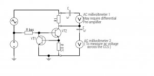
I have redrafted my original scheme to make my intentions clearer, I realize now that it may have suggested that the CCS took its DC power from the combination of the ac and DC sources when in fact the CCS should have been powered from only the DC source. I don't think that this was clear in the original scheme.
R I is the ac current sense resistor, this needs to be small in comparison with the CCS impedance. By measuring the voltage across this resistor the ac current can be found using ohms law. The idea of using a differential preamplifier in this role is taken from Gary Pimm's site. I expect that it would be best to power the preamp from batteries to avoid any ground loop problems.
The CCS impedance is then calculated, again with ohms law, as V(ac millivoltmeter 2) / ac current, as derived previously.
See attached.......
And in the case of the single transistor CCS or the cascode version the base bias would also be derived from the DC supply ( preferably a stiff and clean supply )
Attachments
Last edited:
Don't know if that is right, but it does look much better.
Now the variable current is applied to the load.
And you can measure the effect that has on the CCS.
Now the variable current is applied to the load.
And you can measure the effect that has on the CCS.
Don't know if that is right, but it does look much better.
Now the variable current is applied to the load.
And you can measure the effect that has on the CCS.
Thanks,
I will try it ( but not today as the weather is lovely! 🙂 )and see if the result seems plausible, to that end can anyone advise on a ballpark figure for the impedance of the type of 2 transistor CCS shown in my last post, I'm only looking for an estimate to the nearest decade / order of magnitude, I was thinking around 1~10 Mohm, is this realistic for this circuit?
Last edited:
Thinking out loud again....
Having returned from a beautiful afternoon in the sun, I am back again!
Iam thinking that if the impedance is likely to be a lot higher than 10 Meg, then the ac current is going to be tiny and thus the respective voltage across the current sensing resistor is going to be very small. I am therefore going to have to build a fairly high gain ( 60dB / x1000 perhaps ) very low noise amplifier to get decent results in terms of measuring the ac current and subsequently evaluating the CCS impedance.
Gordon.
Thanks,
I will try it ( but not today as the weather is lovely! 🙂 )and see if the result seems plausible, to that end can anyone advise on a ballpark figure for the impedance of the type of 2 transistor CCS shown in my last post, I'm only looking for an estimate to the nearest decade / order of magnitude, I was thinking around 1~10 Mohm, is this realistic for this circuit?
Having returned from a beautiful afternoon in the sun, I am back again!
Iam thinking that if the impedance is likely to be a lot higher than 10 Meg, then the ac current is going to be tiny and thus the respective voltage across the current sensing resistor is going to be very small. I am therefore going to have to build a fairly high gain ( 60dB / x1000 perhaps ) very low noise amplifier to get decent results in terms of measuring the ac current and subsequently evaluating the CCS impedance.
Gordon.
200k to 300k at DC and falling a lot above the audio band.
Thanks again Andrew, that should be easily measurable with the resources I have to hand. The figure of 1~10 M was suggested by another thread on CCS, I forget which one or I'd have posted a link, the figures were the result of spice simulations.
BTW, how is it you got a Scotland flag? I'm from Stirling ( well Glasgow originally ) and I got a UK flag, its not a big deal, I'm not really the patriotic type, just curious is all.
the Country is an option that the Member chooses.
I was about to make a comment and removed it in case it was interpreted as "politics"
I was about to make a comment and removed it in case it was interpreted as "politics"
To avoid the difficulty of measuring a small AC voltage riding on a much larger one, you can use a FET cascode to reference the error voltage to a steady DC rail. This will make things considerably easier, since you just need a single-ended, sensitive millivoltmeter or measuring amplifier.I have redrafted my original scheme to make my intentions clearer, I realize now that it may have suggested that the CCS took its DC power from the combination of the ac and DC sources when in fact the CCS should have been powered from only the DC source. I don't think that this was clear in the original scheme.
R I is the ac current sense resistor, this needs to be small in comparison with the CCS impedance. By measuring the voltage across this resistor the ac current can be found using ohms law. The idea of using a differential preamplifier in this role is taken from Gary Pimm's site. I expect that it would be best to power the preamp from batteries to avoid any ground loop problems.
The CCS impedance is then calculated, again with ohms law, as V(ac millivoltmeter 2) / ac current, as derived previously.
See attached.......
And in the case of the single transistor CCS or the cascode version the base bias would also be derived from the DC supply ( preferably a stiff and clean supply )
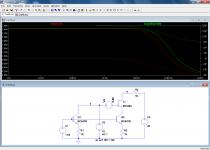
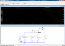
In this example the red trace is the output impedance measured the "traditional" way.
The green one is the result of the cascade isolator. V4 serves to equalize the static Vce's of the two transistors.
You can see that the method is quite robust: even if the measurement shunt is made 5x larger, there is no significant difference in the result
Attachments
To avoid the difficulty of measuring a small AC voltage riding on a much larger one, you can use a FET cascode to reference the error voltage to a steady DC rail. This will make things considerably easier, since you just need a single-ended, sensitive millivoltmeter or measuring amplifier.
In this example the red trace is the output impedance measured the "traditional" way.
The green one is the result of the cascade isolator. V4 serves to equalize the static Vce's of the two transistors.
You can see that the method is quite robust: even if the measurement shunt is made 5x larger, there is no significant difference in the result
Thanks again elvee, This should be quite easy to accomplish, I can use the DC offset on my signal gen to provide the -0.86 v to bias the fet. My 41/2 digit bench dmm should be able to measure the ac voltage at point b on the 20 mV range, I think.
Just to clarify, the test signal is 10 volts DC with 1 volt AC ( peak or RMS ? ) riding on it, that would make the ac collector current around 0.5uA or 0.5mV across
a 1k resistor?
EDIT: If the smallest range on the DMM is only 200mV, perhaps a 20 db / x10 or even 40db / x100 preamp might be in order, I forget if the minimum range is 20 or 200mV ( terrible memory. )
Last edited:
In this example, with a stimulus of 1V, the current into the measuring shunt would be 0.4µA, resulting in a voltage of 0.4mV.My 41/2 digit bench dmm should be able to measure the ac voltage at point b on the 20 mV range, I think.
If that is too low, a simple amplifier made with a TL071 or NE5534 could raise it to more manageable levels.
Yes. The fact that it is peak or rms doesn't change anything provided you use the same format in the calculation of the impedance. The absolute value of 1V does not really matter either. It cannot be too large because non-linear effects will begin to show, or too small because the noise will become an issue but that leaves quite a usable rangeJust to clarify, the test signal is 10 volts DC with 1 volt AC ( peak or RMS ? ) riding on it, that would make the ac collector current around 0.5uA or 0.5mV across
a 1k resistor?
An fet question I've always wanted to ask and relevant here, in terms of the DC component what is the relationship of the voltage at the source and the voltage at the gate? I know that with a bjt its -0.6v and for a MOSFET -2~4 volts (Vth).
Last edited:
In this example, with a stimulus of 1V, the current into the measuring shunt would be 0.4µA, resulting in a voltage of 0.4mV
Can I trouble you to explain why it's 0.4 uA instead of 0.5 uA ?( sorry, I don't have the mu symbol on this tablet so u is used instead, you probably figured this already, but thought I should clarify for any other readers )
- Status
- Not open for further replies.
- Home
- Amplifiers
- Solid State
- How do you calculate impedance of a current source?