For a small signal transistor of planar technology, a rule of thumb to estimate 1/h22 is ~100/Ic (Ic in mA and R in KΩ)Looking at the curves for the bc547, it is essentially perfectly flat at just over 10mA, suggesting that r nought would be very high. The graph has nowhere near the resolution with which you could make a reasonable assessment of r nought.
If the curve is perfectly flat, it's wrong. Va (1/Ro) is almost never over 200 volts, a flat line is infinite Va.
For a small signal transistor of planar technology, a rule of thumb to estimate 1/h22 is ~100/Ic (Ic in mA and R in KΩ)
To be more precise, Ro~VA/Ic where VA is the Early voltage. VA=100V is a fair approximation, although certain devices like the 2SA1381/2SC3503 may have a much larger VA, of the order of 700-800V.
Unfortunately VA is almost never specified in the data sheets, but can be rather easily estimated from the Ic vs. Vce slopes.
It still seems a rather glaring omission. I could understand if specifying parasitic capacitance nonlinearity is a bit of a hassle, but a fairly basic parameter like Early voltage?Unfortunately VA is almost never specified in the data sheets, but can be rather easily estimated from the Ic vs. Vce slopes.
In general, the information is (was?) present under one form or another in the datasheet (for types where this information has relevance, obviously).It still seems a rather glaring omission. I could understand if specifying parasitic capacitance nonlinearity is a bit of a hassle, but a fairly basic parameter like Early voltage?
Here, a Philips datasheet example with the plot of hoe vs Ic.
This is from an old paper databook, if you look at the Fairchild DS for the same transistor f.e., it is much more succinct
Attachments

Thank you everyone, you have given me a lot to think about.
From what you say it is implied that certain transistors would be unsuitable for CCS. Which poses the question of which transistors would be suitable and therefore likely to have hoe or h22 specified?
BTW the bc547 data sheet that I had been referring to was a Fairchild one. Are their data sheets typically lacking in detailed info?
Sorry for all the questions, but I'm still pretty new to discrete design ( opamp guy 🙄 )
This is very interesting, thanks.
Regards,
Gordon.
In general, the information is (was?) present under one form or another in the datasheet (for types where this information has relevance, obviously).
Here, a Philips datasheet example with the plot of hoe vs Ic.
This is from an old paper databook, if you look at the Fairchild DS for the same transistor f.e., it is much more succinct
From what you say it is implied that certain transistors would be unsuitable for CCS. Which poses the question of which transistors would be suitable and therefore likely to have hoe or h22 specified?
BTW the bc547 data sheet that I had been referring to was a Fairchild one. Are their data sheets typically lacking in detailed info?
Sorry for all the questions, but I'm still pretty new to discrete design ( opamp guy 🙄 )
Hawksford wasn't original but its a OK treatment of output Z increasing circuit options:
https://web.archive.org/web/2013012..._lab/malcolmspubdocs/J10 Enhanced cascode.pdf
This is very interesting, thanks.
Regards,
Gordon.
Last edited:
EasyEDA - Web-Based EDA, schematic capture, spice circuit simulation and PCB layout Onlinehas schematic entry and simulation capability which should work in your browser. The sim looks rather similar to LTspice.
Thanks, I will check it out.
TINA-Cloud won't run on Android?
To be honest, I assumed not, but I will try!
Thanks,
Gordon.
Actually, the choice of transistor isn't that important...
- If the CCS must work on low Vce (like 1V) it's more complicated (BC807-817 works well)
- If you got more voltage like 3-4V, then cascode it, at this point the output impedance is almost entirely determined by the cascode base current versus vce variation...
- And if you got even more voltage and you don't cascode it, the output impedance depends a lot on self heating also...
Not necessarily. But if you want a complete control of the key parameters, you need to have them specified for the transistor(s) you chose.From what you say it is implied that certain transistors would be unsuitable for CCS.
In general, the transistors having that type of parameter specified are typically small signal amplification ones.Which poses the question of which transistors would be suitable and therefore likely to have hoe or h22 specified?
Note that hoe or h22 applies to purely common emitter configuration, but does intervene to some degree in the output impedance of a CCS. However, "good" topologies (ie. with a low base source impedance, a high emitter resistance and some additional feedback) tend to reject the effect of this parameter
Yes, as do all "modern" ones from any manufacturer: if you need that kind of information, it is (hopefully) conveyed through the spice model, but this rules out the paper and pencil option (unless you are ready to make some reverse extraction from the models, which looks horrendously painstaking)BTW the bc547 data sheet that I had been referring to was a Fairchild one. Are their data sheets typically lacking in detailed info?
Last edited:
Thanks Elvee,
Stubbornly I refuse to give in and use a circuit simulator until I can understand how the solution is arrived at!
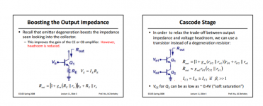
Assuming I can find a value for hoe, Can I substitute 1/hoe for Ro in these equations? ( see attached; from a lecture on current sources at the University of Berkeley )
Presumably in the absence of an actual value for hoe then I can use your suggestion for estimating it, 100/Ic or Ic/100 for Ro since Ro = 1/hoe.
BTW, the design of the Circlophone is very interesting, a bit different to the usual approach to class AB.
Gordon.
Stubbornly I refuse to give in and use a circuit simulator until I can understand how the solution is arrived at!
Assuming I can find a value for hoe, Can I substitute 1/hoe for Ro in these equations? ( see attached; from a lecture on current sources at the University of Berkeley )
Presumably in the absence of an actual value for hoe then I can use your suggestion for estimating it, 100/Ic or Ic/100 for Ro since Ro = 1/hoe.
BTW, the design of the Circlophone is very interesting, a bit different to the usual approach to class AB.
Gordon.
Attachments
Last edited:
That's the correct attitudeStubbornly I refuse to give in and use a circuit simulator until I can understand how the solution is arrived at!
I think soAssuming I can find a value for hoe, Can I substitute 1/hoe for Ro in these equations? ( see attached; from a lecture on current sources at the University of Berkeley )
I found this Siemens data sheet ( old by the look of it ) for the bc556~560 series of PNP signal transistors. It shows hoe is higher for transistors with higher beta. Presumably this would mean that Ro would be lower for the higher gain transistors and consequently less suitable for making a CCS.
Lower beta/HFE would therefore be better for CCS as they would have higher impedance, at least at DC.
Lower beta/HFE would therefore be better for CCS as they would have higher impedance, at least at DC.
Attachments

Yes, that is known fact, and it is confirmed by the Philips DS.Lower beta/HFE would therefore be better for CCS as they would have higher impedance, at least at DC.
For CCS's, as well as voltage amplifiers and some other circuits, a lower Hfe transistor is preferable
no.
The CCS is a DC load, i.e. non varying current.
The Source should be a non varying DC supply.
The bit that varies is the load that the CCS is supplying. The Rload needs to vary. Do this very slowly and you measure the very low frequency response (LF AC impedance) of the CCS
Do it quickly and you measure the higher frequency response.
As far as I can see, applying a variable supply voltage does not mimic the above for a varying load.
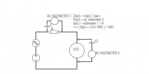
For a simple one-transistor CCS the impedance will be pretty much constant from DC to 20kHz. That being the case, you can measure the impedance simply by applying a DC voltage across the CCS and measuring the current through it. Then increase the voltage slightly, and measure the current again. The difference in voltage, divided by the difference in current, is the impedance. However, be aware that it may vary quite a lot depending on the average voltage across the CCS.I have come up with a scheme to measure the ac impedance of CCS', see attached. Should this work?
If you want to measure the impedance at higher frequencies then you can feed in an AC signal and arrange the CCS as a potential divider, and measure the output signal across R. However, if the CCS is a good one then you may need a large input signal and a very sensitive microvolt meter to detect any signal across R...
An externally hosted image should be here but it was not working when we last tested it.
Using Merlin post37 pic,
moving the sig gen to Vout and moving Vout to be across the lower R gives a variable load and retains the near constant supply voltage into the CCS inputs.
moving the sig gen to Vout and moving Vout to be across the lower R gives a variable load and retains the near constant supply voltage into the CCS inputs.
For a simple one-transistor CCS the impedance will be pretty much constant from DC to 20kHz. That being the case, you can measure the impedance simply by applying a DC voltage across the CCS and measuring the current through it. Then increase the voltage slightly, and measure the current again. The difference in voltage, divided by the difference in current, is the impedance. However, be aware that it may vary quite a lot depending on the average voltage across the CCS.
I'm not sure about this, self heating might mess up the output impedance for very low frequencies: high VCE -> high Pd -> high junction temperature -> lower VBE -> slightly higher current.
- Status
- Not open for further replies.
- Home
- Amplifiers
- Solid State
- How do you calculate impedance of a current source?