Assembling my first LM3875 kit from Audiosector, some advice needed..
Hi Guys,
After luring around these forums, I finally got myself a LM3875 Kit from audiosector. However, I am a complete noob and never built an amp before. I have managed to get the Kits Assembled after referring to the guides.
However, I am completely stuck with this Toroidal Transformer thingy. I am in UK. Here is a pic of all the wires etc. How do I wire it? What goes to the mains and what goes to the Amp? (sorry, I have checked the guides but still being a bit thick)
Can someone help me with the wiring please?
An externally hosted image should be here but it was not working when we last tested it.
An externally hosted image should be here but it was not working when we last tested it.
An externally hosted image should be here but it was not working when we last tested it.
Last edited:
What goes to the mains and what goes to the Amp?
oh lord, I think we better go easy, step by step
")
Attachments
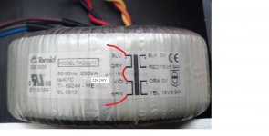
Primary (mains)
Tie gray and violet together to set the transformer for 240v mains, and then blue and brown are the mains input.
Attach earth ground to metal amplifier enclosure.
Secondaries (to bridge rectifier):
Use black and red for AC1
Use orange and yellow for AC2
Using a voltmeter, test everything you can think of per safety. See also, Decibel Dungeon Building a Gainclone chip amp power supply. <--link
Secondaries (to bridge rectifier):
Use black and red for AC1
Use orange and yellow for AC2
I was waiting for someone to post that
but I'm a bit confused about the way it's shown on the toroid, with red wire in the middle(CT)

is this normal color coding ?
the colour coding on the transformer is all quite clear.
The left side is mains or primary.
The red shorting link converts the dual primary to series connected.
That makes it suitable for the 230Vac available in Europe.
The Blu and Brn are the standard colours for mains wiring.
The 8 diodes on the rectifier PCB confirm that the poster has a dual bridge rectifier PSU.
He must keep the dual secondaries separate. There is NO CENTRE TAP.
As stated by Daniel and quoted by you
Use black and red for AC1
Use orange and yellow for AC2
Thanks again guys. I wired it up as per your help. I measured the voltages across v+ and PG+, I think I got 18v - will check again tomorrow. The most important thing is that nothing went BANG as yet..
I am waiting for the slow blow fuse and other bits to arrive, is 2.5A sufficient for this?
Also, I got some silver thermal paste thingy (used the same stuff on my motherboard CPU), would I need to scratch off some of that black paint before applying it?
I am waiting for the slow blow fuse and other bits to arrive, is 2.5A sufficient for this?
Also, I got some silver thermal paste thingy (used the same stuff on my motherboard CPU), would I need to scratch off some of that black paint before applying it?
Also, I got some silver thermal paste thingy (used the same stuff on my motherboard CPU), would I need to scratch off some of that black paint before applying it?
isolating pad ?
amp device should not have metal contact with heatsink/chassis
usually a plastic pad is used
often soft silicone, and no need for additional contact grease(goo)
but device may also be plastic coated
it is hard and mostly means adding contact grease/goo
the key is total electrical isolation from chassis/ground, and still good contact with fast heat transfer
usually a plastic pad is used
often soft silicone, and no need for additional contact grease(goo)
but device may also be plastic coated
it is hard and mostly means adding contact grease/goo
the key is total electrical isolation from chassis/ground, and still good contact with fast heat transfer
If the tab and back of the amp chip is black plastic, such as LM3875TF, LM3876TF, LM3886TF, the insulation is already built in.
If the tab on the amp chip is silver, that conducts V- voltage and Requires a thermal pad to electrically insulate from heatsink and a Shoulder Washer to insulate the screw, plus extra stable mounting so the chip doesn't spin off the pad.
The black aluminum oxide coating doesn't need to be removed from a heatsink before installing the chip amp.
Generally a high performance non-conductive thermal compound works well for chip amplifiers, for example: Arctic Ceramique or GC Waldham Type 44.
Silver compound is conductive and therefore Not recommended but can be used on the "TF" pre insulated chip, if when compensating for a very roughly textured heatsink (silver/copper paste is gap filler), and it takes special attention to keep the silver paste Away from the pins.
Last edited:
2.5A seems too high.....................I am waiting for the slow blow fuse and other bits to arrive, is 2.5A sufficient for this? ................
At 220Vac a T2.5A allows 500W from 550VA transformer
At 115Vac a T2.5A allows 270W from a 300VA transformer.
What is your mains supply voltage?
Hi guys,
So, after a couple of days of measuring, re-measuring, drilling, checking instructions and posting questions here - I think I made some progress (pics to follow)..
This is a TF chip from AudioSector (all black and no metal bits). I used this "Arctic Silver 5 Thermal Compound" paste to attach the chip to chassis (use the same stuff for my PC). http://www.amazon.co.uk/gp/product/B000OGX5AM
I am uk, so mains are 230v (?) but I have not measured exactly. I will check. Given that I am using 250VA transformer, what Amp "Slow Blow" fuse should I be getting?
and some pics..
Is this the correct way to "Star Ground"? I have joined the ground wires from the following to a single point on the chassis:
Mains Ground
PG1+ and PG- (rectifier)
Left amp OG
Right amp OG
Thanks
An externally hosted image should be here but it was not working when we last tested it.
An externally hosted image should be here but it was not working when we last tested it.
Is this the correct way to "Star Ground"? I have joined the ground wires from the following to a single point on the chassis:
Mains Ground
PG1+ and PG- (rectifier)
Left amp OG
Right amp OG
Thanks
T1A suits 240Vac and 250VA.................I am uk, so mains are 230v (?) but I have not measured exactly. I will check. Given that I am using 250VA transformer, what Amp "Slow Blow" fuse should I be getting?
Use a soft start to limit transformer starting current, so that the close rated fuse does not blow.
Thanks Andrew. I will change the fuse.
I powered up the amp today and its sounding sweet. However, I have a distinct buzzing/hum from the actual amp board. Its like the hardware is making the buzz, but I do not hear it in the speakers, just directly from the amp.. Any ideas?
I powered up the amp today and its sounding sweet. However, I have a distinct buzzing/hum from the actual amp board. Its like the hardware is making the buzz, but I do not hear it in the speakers, just directly from the amp.. Any ideas?
The transformer, she may be excited by that layout.
You could bolt the amplifiers to the actual heatsink (the big finny looking things on the sides of your enclosure are the heatsinks where the amplifier is supposed to go) and move the bridge rectifier and make more space for the transformer and then give the transformer some clearance.
Even so, the transformer may still need some good rubber pads on top and bottom.
P.S.
Question: Using light bulb tester jig, does it go bright when the amp is on and not playing?
Last edited:
- Status
- This old topic is closed. If you want to reopen this topic, contact a moderator using the "Report Post" button.
- Home
- Amplifiers
- Chip Amps
- How do I wire this Toroidal Transformer to LM3875 kit from Audiosector?