What's the purpose of the extra 100k?Works like a champ for me, pretty deep nulls and only two adjustments, per post #5
That's the bias resistor for opamp pin3. Imagine that nothing is plugged into the input jack; where does pin3 bias current flow?
The input sees the source and if there is a loading resistor at the Source/oscillator output, then the FET input opamp gets a biasing load back there.
Is there an advantage to taking the biasing resistor until after passing through the two R limbs?
Rather than taking the biasing resistor at the +IN pin of the FET input opamp?
Is there a ratio of biasing resistor for R+R:100k that needs to be used to maintain accuracy of the notch?
Another notch circuit uses 1M:7k+7k where the 1M is at the +IN pin.
Last edited:
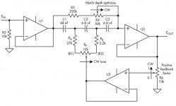
Yes there is an advantage to positioning the 100k bias resistor at the far left rather than at the far right.
Try both in simulation and step the bias resistor value 10K, 100K, 1Meg. This generates six output traces, three for "resistor_at_left" and three more for "resistor_at_right". I predict you will prefer the traces for "resistor_at_left".
Try both in simulation and step the bias resistor value 10K, 100K, 1Meg. This generates six output traces, three for "resistor_at_left" and three more for "resistor_at_right". I predict you will prefer the traces for "resistor_at_left".
I have to thank you for trying to help, but that is no help to me at all.
I will just have to accept that at the left is better.
I will just have to accept that at the left is better.
This came up in the low distortion oscillator thread, I forgot whose name is on this but there were some references in that thread last week. I simmed it and it worked great. It also works as a passive filter without the op-amp and Q enhancement response is then identical to twin-tee but with one pot frequency trim.
This is the hall network filter. Lots on the net about this. Just google it.
The Hall Network A one-pot Tunable Notch Filter - traktoria.org
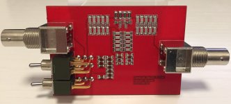
The Hall network filter works great. With Samuel's PCB and using 1% C0G caps, it's possible to match C to below 0.05% by grouping. Then with 0.1% 25ppm kit resistors, a notch depth of 88dB was reached at the desired frequency without much hassle.
Attachments
Last edited:
The Hall network filter works great. With Samuel's PCB and using 1% C0G caps, it's possible to match C to below 0.05% by grouping. Then with 0.1% 25ppm kit resistors, a notch depth of 88dB was reached at the desired frequency without much hassle.
Was that untrimmed I don't see a pot?
OT - I wonder how you apply a 1% 5pF cap, you would need some bridge setup to even measure it.
Was that untrimmed I don't see a pot?
OT - I wonder how you apply a 1% 5pF cap, you would need some bridge setup to even measure it.
There is no pot for trimming. The procedure is first to populate the 30k and 10k resistors and then measure the notch frequency. Then calculate the value of the tuning resistors and add them (there are parallel and series resistors for tuning). It works easier than expected.
The capacitors are 1nF.
There is no pot for trimming. The procedure is first to populate the 30k and 10k resistors and then measure the notch frequency. Then calculate the value of the tuning resistors and add them (there are parallel and series resistors for tuning). It works easier than expected.
The capacitors are 1nF.
That's what I thought, at least it looked that way and it's good to know you don't need a lot of iterations. I was just surprised they make 5pF 1% capacitors you would need 50 femtoF parasitics to preserve that.
This is the hall network filter. Lots on the net about this. Just google it.
The Hall Network A one-pot Tunable Notch Filter - traktoria.org
Interesting circuit! Here are some clickable links:
Rediscover The Truly Tunable Hall Network | Analog content from Electronic Design
http://traktoria.org/files/radio/filter_design/hall_network_a _one-pot_tunable_notch_filter.pdf (opens PDF)
http://traktoria.org/files/radio/filter_design/design_and_applications_of_the_hall_network.pdf (opens PDF)
Last edited:
I used the DMM setting of 200.0nF. It reads 22.1nF for the two that were fitted into the low cap arms.Was that untrimmed I don't see a pot?
OT - I wonder how you apply a 1% 5pF cap, you would need some bridge setup to even measure it.
The two that read 22.0nF and 22.2nF were paralleled to fit in the high cap arm.
I guess my very inaccurate DMM has given me better than 0.5% matching.
And the final notch depth for the passive filter, with resistor trimming, gets me to -88dB to -89dB
Last edited:
Three questions about a hall filter. First what is the tuning range? Second can a relativly small notch depth (40dB) be obtained and how much does the notch depth change with frequency? Third can feedback alter the Q and depth of the notch?
Ill try a simulation soon but someone may already have some answers.
Sent from my LG-H811 using Tapatalk
Ill try a simulation soon but someone may already have some answers.
Sent from my LG-H811 using Tapatalk
Three questions about a hall filter. First what is the tuning range? Second can a relativly small notch depth (40dB) be obtained and how much does the notch depth change with frequency? Third can feedback alter the Q and depth of the notch?
Ill try a simulation soon but someone may already have some answers.
Sent from my LG-H811 using Tapatalk
At a given frequency tuning is not bad but does effect all other parameters.
Notch depth, Q etc. One would have to have to pots. Tuning and notch depth.
It looks just the same as a TT when FB is applied.
By the way the FB is really just a bootstrap. Is there a passive way of achieving this?
Three questions about a hall filter. First what is the tuning range? Second can a relativly small notch depth (40dB) be obtained and how much does the notch depth change with frequency? Third can feedback alter the Q and depth of the notch?
Q(boost_factor) = 1/(1-PFF)
Attachments
I was able to get a reasonably good pull up with the feedback just using resistors without the extra op amp.
Hello Andrew,
When building a notch filter for THD analysis and measurements we look often for a deeper and sharper notch response
while that is probably not that gave us the better chance to get a right result.
I think that before all, it is need to know with confidence what is the THD of the acquisition system
( from the notch output) to any signal level, and particularly at the level delivered by the notch output.
Many ADC still have spurious and harmonics with level that doesn't decrease significantly with a lower signal level.
When using a very good oscillator and a stepped attenuator (easy to do with some resistors),
it is easy to verify that the analyzer itself doesn't produce any THD at the level you will get at the output of the notch.
When using a notch filter including active part (OPAMP), a better way is also to have the possibility to switch
before the active buffer between the notch itself and a passive attenuator.
This passive attenuator must have the same attenuation of the notch filter at the tested frequency .
Then, it is easy to check by using this switch if the harmonic content is different with the notch or with the passive attenuator.
Note also that if you try to see very low signal level, the building of the filter must be very clean (short and direct path),
and shielding will become mandatory. Use also a low noise PSU or some batteries.
Of course for signals : coaxial connectors
I built three notch filter boxes, two Twin-T and recently a new using the Hall network
(reading a post on the "low distortion audio range oscillator" thread).
That i can say is that both work fine.
The Hall can be adjusted more easily but each "depth" and "Fo" trim are dependent so they need to be trimmed both.
Anyway, It's still easier to adjust than my Twin-T.
The Hall need some feedback to avoid high attenuation of harmonics.
I used two AD797 with a little notch feedback but no output gain.
When testing the EOSC10KV3 10kHZ oscillator, i don't see any spurious or harmonics content.
Of course if you try to measure much higher THD level the task will be more easy, but care is the rule in measurement .
Regards.
Frex
someone asked about Dick Moore's website. As you see, it is gone from active web presence. That is where "the wayback machine" comes in handy. That is a searchable internet archive available to all. Dick's web page lives on there, fully accessible.
https://web.archive.org/web/20161024123617/http://moorepage.net/Twin-T.html
all hail the ghost in the machine
and thanks Dick for your generosity in life, RIP
Cheers
Alan
https://web.archive.org/web/20161024123617/http://moorepage.net/Twin-T.html
all hail the ghost in the machine
and thanks Dick for your generosity in life, RIP
Cheers
Alan
- Status
- Not open for further replies.
- Home
- Design & Build
- Equipment & Tools
- How do I tune my Twin T notch filter ?