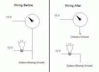
I am having trouble with some gauges I am putting in my car. I have a Subaru, and as I recall, Subaru uses a moving ground for dimming interior lights, not a moving source.
This gives me troubles, because in my gauges the dimming circuit and the gauge servo power circuit share the same ground. Thus, when I dim my lights, my gauges don't receive enough voltage to operate properly. This annoys the **** out of me; I go to dim my interior lights and the gauge needles fall down.
I would like to fix this problem with a circuit workaround, but I'm unsure where I should start.
The first thing I have to do is find out what is normal for a dimming wire in an automobile. Is the voltage range 0-12 Volts, 11-12 Volts, etc... I don't know what the "standard" voltage difference between fully illuminated and unilluminated is in automobiles.
Next, I have to take some measurements from my car, and find out what the voltage difference between fully illuminated and unilluminated is for my particular application.
Finally, I need to make a circuit that operates on the voltage difference of the moving ground, and transfers that to an equivalent voltage difference on the positive side. Then, I should be able to have the gauges dim correctly while operating correctly.
I've done a ton of custom work on the gauges for my car. I've redone the gauge faces to match the interior of my car, did custom work on the gauge housings, and hooked an 86 db Piezo buzzer to warning lights on my gauges so I get a loud warning if something gets too hot or too low (a big thanks to diyaudio on this design as well). Getting the gauges to dim correctly is that last thing I have to do.
I've spent a ton of time on these gauges, but I've learned a lot about circuit design and have enjoyed every minute of it. I hope I can solve this one last little nagging issue and then the gauge project part of my car will be complete. All that's left then is to tweak the suspension, get her up to 350-400 HP, and get the datalogger in place. Then you can find me on the track 🙂
Usually fully illuminated lights are running from 12V. Not sure about anything else though....do you have a circuit diagram?
Anyway, from one car guy to another....I like the machine you've got...hopefully you can finish everything!
Anyway, from one car guy to another....I like the machine you've got...hopefully you can finish everything!
Obviously I cannot be sure without seeing the gauge in front of me, but based on what I have seen, my guess would be that it would be far far less effort to disassemble the gauge, isolate the light bulb socket from the common ground wire, solder on a new wire, and then just hook up the 2 light bulb wires in Subaru-polarity. Usually aftermarket gauges have good access to the lights for replacement purposes.
Thanks guys. After Thinking about it some more I think you're right, it would be simpler to isolate the lighting and hook it to the Subaru moving ground, and hook the gauge operation wire to a "real" ground on the chassis. I forgot there's more than one way to skin a cat.
- Status
- Not open for further replies.
