Hi,
I am going to try an hybrid Mu follower (aka Moglia Gyrator)for an ECC88. And I need some help, please.
I read on Ale's site the formula is 1/Gm. Is Gm the Mu of the tube? So here 33 which gives 1/33=0.0303,equal to 303 ohms or something else ?
About the littler J-Fet I saw the use of the J310 (I go diy and use To90 for factor, not soic) and the choice what about the mA you need, is it about the anode curent limit of the tube anode for the Jfet choice ? How to choose this J-fet please ? (J310, BFA245A, J113... I have few on hands)
How about the last flavor of the big Mosfet today and how much volts the circuit has to drop to work fine - anode will go with around 75V-.
mu = gm x rp
gm is the small signal transconductance in units of Amps out per Volt in (Siemens)
rp is the small signal internal plate resistance in Ohms
mu is the small signal change of vpk vs change of vgk with ip constant (unitless)
See page 10, where gm is called S for its units of Siemens.
See page 8, gm is the slope of the curve at the operating point.
Attachments
Last edited:
Hello,
The more I look at it, the more I do not understand what you explained to me rayma.
Seems I need the gm to calculate the resitor ohm value for the gyrator which is 1/gm. But seing page 10 I do not understand which value must be chosen on the S curve of page 10.
I know i will power the anode with 75 V, is it needed to find what I'm looking for or is there a unique spec of gm in the datasheet ?
Could you please illustate what you wrote please ?

Most low gain triodes being used today(6sn7 ,12au7) have a GM of approximately 2.5 to 3mA/v so the equation for those tubes would come to about 400 to 500 ohms. I actually use a gyrator loaded 12au7 with a 470 ohm resistor in that spot.
The ECC88 has a GM that is 4 to 5 times larger (12.5mA/v) than the 6sn7 etc. hence the difference in the Ohms figure in the equation .It was also a big selling point of that tube when released.
It's really an oddball in that regard.
The ECC88 has a GM that is 4 to 5 times larger (12.5mA/v) than the 6sn7 etc. hence the difference in the Ohms figure in the equation .It was also a big selling point of that tube when released.
It's really an oddball in that regard.
a bit too late to answer, but I just build and used two of those as drivers for 300B, using 6N7, in any case, Gm that was mentioned above is not tube's Gm so do not check those datasheet, but it is a Gm=Gfs of jfets, and on the website there are actually recommendations for Rmu values:
2SK170 - 1k5
BF862 - 330-470 Ohm
J310 - 1k-1k5
2N7000 - 330-470 Ohm
The suggestion to use IXTP01N100 for B+ higher than 300V is good, but M3 (that transistor) will never see high voltages because it only sees the difference between B+ and Vref (see the schematics). So even with B+ of, for example, 450V, when Vref is about 150-250V DN2540s also working very nicely.
And as a last suggestion, one does not have to create B++ from B+ with this hybrid model (via extra RC network), so we do not need lots of caps (it is also described in the manual).
The suggestion of 1kV FET over -about- 300V is based on experience: the most of DN2540 may destroying at startup voltage spike using B+ over 300V.
I lost a few dozen of this type FET.
I replaced its later to 1kV Ixys, and the malfunction is eliminated.
I lost a few dozen of this type FET.
I replaced its later to 1kV Ixys, and the malfunction is eliminated.
Indeed, it might be something practical. Theoretically there is no B+ between S and D of that transistor in any given moment, taking into account that mu-follower is fed via RC or LC network. The tube will never set it to ground and the voltage reference is as fast as voltage at RC/LC, so the transistor is always between B+ and Vref (and the difference between those two of course should not be >400V, the specs breakage voltage). Probably the quality of the parts makes then break under different conditions. Strangely, I cannot source right now IXTP01N100 or IXTP08N100, the lead time is huge, but there are plenty of IXTP8N65 or IXTP2N65 (650V). I would have to check the specs if those would be a good match.
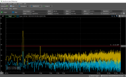
I played a bit with my setup of that hybrid mu follower, specifically Rmu and I got some interesting results, which are bit unexpected. Probably it will be useful to put them here for the future. I use the mentioned schematics, with B+ of 400V, 6N7 tube, Vref set to 275V and current of 9ma. The transistors are DN2540 and 2N7000. The Gfs of 2N700 is 360 which translated to Rmu of 270 Ohm. The designer of that circuit suggested 330-470 Ohm, because the stated in the specs Gfs is for Vds= 10V, but in the described circuit Vds is smaller so the transconductance should be adjusted. In any case, I get nice amplification of 35 times in all cases, which perfectly matched the stated tube's mu of 35,, but the spectral characteristics are totally different. Only for Rmu of 270 ohm I get very low background of about -70, -75dB but as can be seen in the plots also the third harmonic. For Rmu or suggested 370 or 470ohm, I get very similar results for the fundamental and 2nd, but the noise/background level increases a lot and the 3rd harmonics is not visible (but most likely it is just masked by the increased level). The harmonics are actually there because I am pushing that tube quite far, to have clean 210Vpp output with 6Vpp input, even though for my 300B stage I only need 150Vpp.
Attachments

OK, probably one possible explanation is that different brands of 2N7000 apparently have quite different values for Gfs, for example here it is 320mS https://cdn-reichelt.de/documents/datenblatt/A100/NDS7002A-D.pdf and here is it 600mS https://www.st.com/resource/en/datasheet/cd00005134.pdf and here it just says minimum 100mS https://cdn-reichelt.de/documents/datenblatt/A100/2N7000_ENG_GER_DS.pdf and some do not even mention it https://cdn-reichelt.de/documents/datenblatt/A100/2N7000-UTC.PDF which should effect Rmu, so be aware while following the manual.
Hi istealth - just wondering if you could show me where to find those references on Ale's website (we could pm each other if that is more convenient).a bit too late to answer, but I just build and used two of those as drivers for 300B, using 6N7, in any case, Gm that was mentioned above is not tube's Gm so do not check those datasheet, but it is a Gm=Gfs of jfets, and on the website there are actually recommendations for Rmu values:
2SK170 - 1k5
BF862 - 330-470 Ohm
J310 - 1k-1k5
2N7000 - 330-470 Ohm
Btw, for 2SK170 I have actually been using 1K Ohm (at around 14mA).
I think that the amount of bootstrapping you need is related to a few things - one is obvious: How much you current you are biasing for. The other is how much power (and voltage drop) the upper device is dissipating.
If the upper device is dissipating a lot, then the lower device probably needs less bootstrapping. Less bootstrapping probably results in less noise but there will always be some bootstrapping required. In my circuit, the upper device is dropping around 250VDC 😉
Also, as Ale notes the quality of the bootstrap resistor (R-mu) is very important. You can't just fiddle around with some multi-turn cermet pot here. You need a film resistor.
Ian
Last edited:
Hi Ian,
At some point I found the manual here https://www.bartola.co.uk/valves/wp.../07/Bartola-Gyrator-PCB-Build-Guide-Rev07.pdf
I am not sure if the newer version exists somewhere. The info in on page 3 there.
My circuit in that case is biased for 9ma, the top transistor drops 150V, and the lower of course cannot drop more than 12V because it is shunted with a zener diode.
With the values of Rmu, in order to have exactly the same experimental conditions I indeed was using a separate metal film resistor 5%, so now doing potentiometers. If I have time I will try to go with that resistor slightly lower and measure the spectrum, but I am pretty happy with the behaviour, one cannot avoid those 2nd and 3rd harmonics with triodes anyways🙂
- Home
- Amplifiers
- Tubes / Valves
- How calculate the Rmu resistor in an hybrid Mu follower