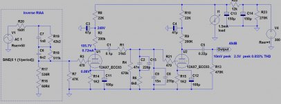
Why not use inverse RIAA?
Without it, the transmission curve distinctness is indiscernible.
With such low (25uF) cathode capacitor the bottom part of curve is sloping. Try to use greater (for example 100uF) good (BG, Elna Silmic etc) capacitors.
Unnecessary to use 0.47uF as RIAA stage coupling capacitor (too large).
If you insist such low value RIAA parts, you will probably need serial resistor for proper RIAA correction.
Try to decouple EACH stage from PSU (I use RC for each stage).
I trim each RIAA capacitor with small (1.. few hundred pF) value styroflex or silver mica capacitor.
With these values the gain is a bit high (48dB) -more noise- , so 5751 is usable.
Attachments
Why not use inverse RIAA?
Without it, the transmission curve distinctness is indiscernible.
I am not sure what you mean AFAIK this whole circuit is inverse RIAA.
With such low (25uF) cathode capacitor the bottom part of curve is sloping. Try to use greater (for example 100uF) good (BG, Elna Silmic etc) capacitors.
Good idea
Unnecessary to use 0.47uF as RIAA stage coupling capacitor (too large).
Yes I started with high value so that I didn't have to change it as I played around with other circuit values and layouts then never went back to figure best values.
If you insist such low value RIAA parts, you will probably need serial resistor for proper RIAA correction.
It is not so much insisting on particular values it is just laziness 🙂 I just used the value of rp||rl as source Z in online calculator. I did consider adding an external source resistor as you did and recalculating the EQ network to minimize the effect of variation in rp. Down side is higher Zout for the stage (and maybe some additional noise) but probably worth doing.[/quote]
Try to decouple EACH stage from PSU (I use RC for each stage).
I trim each RIAA capacitor with small (1.. few hundred pF) value styroflex or silver mica capacitor.
With these values the gain is a bit high (48dB) -more noise- , so 5751 is usable.
Yes, for this stage of devolopment I simplified with battery as PS. In practice I usually RC decouple each stage.
Interesting that you bypass the RIAA caps. I would have thought that the film caps would be fine without it. I would.consider bypassing the electrolytic Rk with film but would have never thought of it in the network. What parameter specifically does that improve?
I could use 12AY7 for second stage to lower gain. Unbypassed Rk on second stage is another option but raises Zout. Since the ceramic cart input is probably close to 1 meg that might not be a problem. 12AY7 will probably require a little more current from the host PS but probably not too much. I am also considering cheating a bit by modifying the phono input on the host console by reducing input resistor for lower noise.
Thank you for very valuable input.
I am not sure what you mean AFAIK this whole circuit is inverse RIAA.
Do you know Jim Hagerman's article?
http://www.hagtech.com/pdf/riaa.pdf
It's purchasable ( https://hagerman-audio-labs.myshopify.com/products/iriaa2-inverse-riaa-filter ), but -if you have enough accurate C measurement instrument- DIY building is easy.
Without such this devices the phono stage development -even in simulator- is pretty hopeless (I made my very first iRIAA tool from about thirty years ago).
In case of real measurement the correction values trimming almost unavoidable. I prefer C trimming with good few..few hundred pF value capacitors, than R trimming, but it's a matter of taste.
Oh, OK. You are talking about the extra ultrasonic corner frequency(ies). I might consider that on the original phono pre that this post was about (the cascode input one) since that is for a general hifi preamp. This last one is for use with console stereos and neither my ear nor the unit is going to be doing much of anything at 50kHz (or even an octave lower) so I am content for this one to allow the response to continue to fall and take any ultrasonic noise with it.
I really don't have a good measurement set up in any case so stressing about utmost accuracy won’t really do me any good at this point anyway. 🙂 I think part of my confusion was the conventions (or lack thereof) for what is RIAA and what is Inverse RIAA. I think of the pre-EQ applied to the cutting head as RIAA curve and what the phono preamp does as Inverse RIAA. Thus the box you provided a link to (pretty cool thank you) would be an RIAA curve device not an Inverse RIAA device. Of course since we hobbyists talk about our preamps as the RIAA curve, lazy folks that we are, it can be confusing.
I really don't have a good measurement set up in any case so stressing about utmost accuracy won’t really do me any good at this point anyway. 🙂 I think part of my confusion was the conventions (or lack thereof) for what is RIAA and what is Inverse RIAA. I think of the pre-EQ applied to the cutting head as RIAA curve and what the phono preamp does as Inverse RIAA. Thus the box you provided a link to (pretty cool thank you) would be an RIAA curve device not an Inverse RIAA device. Of course since we hobbyists talk about our preamps as the RIAA curve, lazy folks that we are, it can be confusing.
Last edited:
Another note WRT the console adapter preamp, the first console I intend to use it on oddly enough has a 6EU7 as the VAS stage on the PA chassis. If that tube is actually working I am tempted to use it as the first stage of the phono adapter and rewire the console to use 12AX7.
P.S. In cases like 6EU7/12AX7 and others where tubes are interchangeable except for heater and/or pin assignments is there any technical reason why one should not have two sockets both wired into the circuit in parallel so that either tube can be used plug and play by simply using the right socket as long as one never populates both sockets or uses the wrong one?
P.S. In cases like 6EU7/12AX7 and others where tubes are interchangeable except for heater and/or pin assignments is there any technical reason why one should not have two sockets both wired into the circuit in parallel so that either tube can be used plug and play by simply using the right socket as long as one never populates both sockets or uses the wrong one?
Hi mashaffer
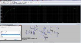
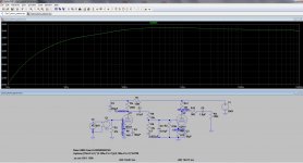
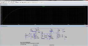
Your circuit corrects for RIAA so it helps to have an inverse RIAA source. When you then simulate you should see a nice flat frequency response curve.
Try adding an "e" component after your signal source, then add a laplace equation under the "value" attribute for the inverse RIAA correction.
I use laplace ((75e-6*s+1)*(3.183e-3*s+1))/(3.183e-4*s+1)*9.8759
Yes, it has a bit of a fudge factor at the end of it to try and get 5mV input ~= 5mV output.
Look at my screenshot.
Attachments
Last edited:
Ah, I see euro21 has also posted a method of introducing an inverse RIAA source.
I think both ways work well enough.
I think both ways work well enough.
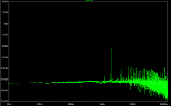
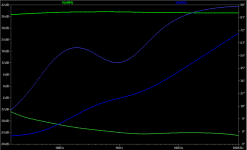
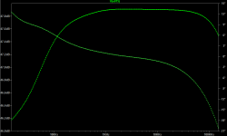
OK, Tried with 12AY7 second stage and it looks really good. I will try messing with the pre-eq that you guys have suggested and see what it looks like but this version shows max gain of 61dB HD2 -63dB and all others -110dB or better @ 1KHz (of course simulation only for comparison).


Attachments
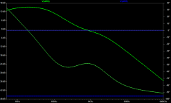
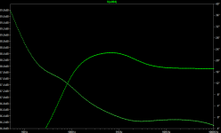
Hmmm... Only a 0.5dB bump around 700Hz (not a big deal) until below 150 Hz drops like a rock. I must have done something wrong as the raw response shows no reason for that. ???


PS. Looking at the scale again I guess it is only 3dB down at 16Hz. that is certainly acceptable.
PS. Looking at the scale again I guess it is only 3dB down at 16Hz. that is certainly acceptable.
Attachments
Last edited:
You're getting closer. Try to use the word laplace before the formula...
Your output will require a coupling capacitor. I prefer to use a follower, but maybe you won't be using any cable interconnect?
Also, Euro21 is very much right with his suggestion to decouple each stage with an RC. You will see that I left this in the schematic.
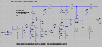
Look at my screenshot sim of one of your recent circuits.. I am using Ayumi Nakabayashi's models in my LTSpice...
Ian
Your output will require a coupling capacitor. I prefer to use a follower, but maybe you won't be using any cable interconnect?
Also, Euro21 is very much right with his suggestion to decouple each stage with an RC. You will see that I left this in the schematic.
Look at my screenshot sim of one of your recent circuits.. I am using Ayumi Nakabayashi's models in my LTSpice...
Ian
Attachments
ok, I think you are getting it now. So go back and look at my screenshot in post #46. See how flat it is? Also look at the gain.
I think 12ay7 is not really a great choice, but that's up to you... I find it better to use 12ax7 then a follower, so output impedance is low enough to drive signal through a cable.
The mosfet follower is an excellent quality dirt cheap solution here. I always thank Eli Duttman for mentioning this. 😉
🙂
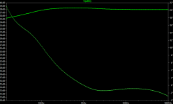
The word laplace is in the E description. What you see on the schematic is just a lable that I used for cut and paste purposes. Still haven't gotten around to including the PS decoupling. :} Actually our curves look very similar. I notice you also have a low midrange bump. Must be built in to this type of circuit. For that little bit of error it doesn't seem worth splitting them up to me.
Using another 12AX7 would be excellent but I end up with an extra 10-12 dB gain which seems excessive. Is that not a problem? I always thought the AY a nice tube. What do you dislike about it?
If this ends up on a separate chassis it will be within a foot of the amp chassis so very short cable. Zin of the amp will be in the 0.5M-1M so I suspect the AY would have no problem driving it. Not sure about the AX but that is a pretty short run into a high Z. That said I have gobs of AXs and AUs so two AXs plus an AX or AU CF would be no problem.
Hi Mashaffer
You can use 12ay7 but just keep in mind that it has a reputation for being the least linear of those family of triodes.
The DC load line you chose is steep, but it looks fairly linear at that bias. The AC load line will be only marginally steeper if you direct couple it to the follower. You can of course choose to use 12ay7 as the follower as well.
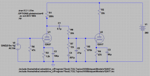
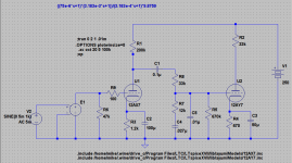
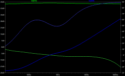
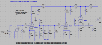
In the circuit above, C1 can easily be 0.22uF and if you can make C5 a bit smaller your RIAA correction should be a bit flatter. Also, your RC network for the 1st triode can easily use a higher value (helps to further reduce psu ripple). I picked 47k ohm in this example - you see the plate voltage is still around 90, which is quite ok for the chosen bias.
The small value resistor in series with the coupling cap on the cathode of the follower is useful to prevent RF interference. Hope you're using DC heaters. Take a look at my screenshot.
Ian
You can use 12ay7 but just keep in mind that it has a reputation for being the least linear of those family of triodes.
The DC load line you chose is steep, but it looks fairly linear at that bias. The AC load line will be only marginally steeper if you direct couple it to the follower. You can of course choose to use 12ay7 as the follower as well.
In the circuit above, C1 can easily be 0.22uF and if you can make C5 a bit smaller your RIAA correction should be a bit flatter. Also, your RC network for the 1st triode can easily use a higher value (helps to further reduce psu ripple). I picked 47k ohm in this example - you see the plate voltage is still around 90, which is quite ok for the chosen bias.
The small value resistor in series with the coupling cap on the cathode of the follower is useful to prevent RF interference. Hope you're using DC heaters. Take a look at my screenshot.
Ian
Attachments
Last edited:
Thank you. Will do some more playing around. Since I am stealing B+ from the console I thought I would dig through my stash of wall warts and see if I have a DC one of sufficient V and I to provide DC heaters with some additional filtering. If not I will have to build one myself. I don't think the host console can provide the extra heater current.
Is AY7 really less linear than the AU7? That surprises me. I like the AY's more moderate mu and resistance to microphonics compared to the AX7.
Is AY7 really less linear than the AU7? That surprises me. I like the AY's more moderate mu and resistance to microphonics compared to the AX7.
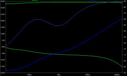
I wouldn't bother with RC decoupling between the follower and 2nd gain stage.
If you right-click the left hand scale (phase) you will get a pop-up where you can select not to show phase.
I am actually looking at the plate curves for both 12ay7 and 12au7 and must admit that 12au7 does appear even worse. Go figure. In any case, the chosen operating point for the 12ay7 does look decent, so if you want a bit less gain then feel free to use it. 🙂
Ian
goodness. I just looked up how much 12ay7's go for on that auction site. Seriously, consider the mosfet follower. no heater with the mosfet follower too.
- Status
- Not open for further replies.
- Home
- Source & Line
- Analogue Source
- How about this phono idea