how do i check for the power supply faults? Or is that what you mean about changing out all the filter capacitors for IC?
the output tubes are glowing so i am assuming that they have power going to them. I did notice that the schematic you have is a newer revision than the one I have. Mine is dated 1996. Is there a difference between the one i have and the ones you posted or all the deville's the same? i have the hot rod deville.
Hmm, This is going into a never ending story style of repair.
So let's have a look.
1. It's no use to "try" other tubes, change caps or resistors without asking yourself: "What's the purpose of doing it. What am I doing?"
2. As Enzo said: "Isolate the B+ problem."
3. How to do that?
Write doen the following positive voltages you have with the amp out of standby:
on C31, C33, C35, C36 and in that order.
(eg. C31 +480, C33 +475, C35 +435, C36 +375)
In repair you have to follow a method; All the rest is rubish...
Do it first with no tubes in the amp.
Then write down the values with the tubes in the amp.
This will make things a lot clearer.
All the other tips and tricks; leave them for later.
First thing first: Your B+ as said by Enzo.
Come back with the numbers and do not try to do anything else after we checked them.
If you change something while we are reading your answer, we and you can come to a wrong conclusion.
And that's not what you're after.
Different revisions have some differences, but those changes may have nothing to do with your issues, or they may. Your schematic is dated 1996 or the board in your amp is? About 2001 I think is when they went to one board for both DeVille and Deluxe in the Hot Rod series.
Clearly if they changed the tone controls, it would not affect a high voltage problem for example.
checking for faults means exploring the circuit looking for missing or wildly wrong voltages, etc. JUst changing a bunch of part "just because" is not checking anything.
The heater glowing inside a tube tells you only one thing: that the heater works. It tells you nothing about the other power supplies. A 6L6 looks the same with and without high voltage.
Tarzan and Enzo, first of all, I really appreciate your help. Tarzan, here are the values as you told me to do them:
Without tubes
C31: 458
C33: 458
C35: 456
C36: 452
With tubes
C31: 344
C33: 343
C35: 300
C36: 247
I won't touch anything else...
Without tubes
C31: 458
C33: 458
C35: 456
C36: 452
With tubes
C31: 344
C33: 343
C35: 300
C36: 247
I won't touch anything else...
So that's that.
The voltages are on the low side but the relationship between them seems ok.
As Enzo propposed:
"the primary center tap of your output transformer is a red wire on terminal post CP18. Disconnect that wire from the post, and see if the voltages on those main filter caps comes back up to close to the 440-485 the schematic calls for."
Leave the tubes in and come back with the value of C31.
If the value is around the 450 or so volts, then I think we have a problem with the output transformer.
It could be that one of the diodes, CR4 and CR5 is shorted to ground but allthough unlikely; it's worth to check them then.
If this dosn't help, then remove the smaller tubes, V1 .. V3, one by one and measure the voltage on C31 after each removal. Start with v3 and proceed to v1. (Place the amp in standby before removing each tube) This way you can see if one of the tubes is drawing to much current.
Come back with the values.
I unplugged R18 and checked the voltage at C31. It was at 365.
I plugged R18 back in and pulled one tube at a time, checking the value of C31 after each one.
After pulling V3, C31 was 357
After pulling V2, C31 was 364
After pulling V1, C31 was 369.
I wasn't sure if I was suppose to leave the tubes out after each pull, so this is with each tube consequently pulled, which I assume is why the voltage would go up a bit each time. On my PCB it didn't have it labeled as CR4 and CR5, it had them as D4 and D5, respectively, but they were in the same place as the schematic shows. I checked each for continuity, not sure if that is what you asked, but these were the values:
CR4-1466
CR5-1473
I did notice that when R18 was unlatched, there was no hum but I am assuming because this is AC power.
To make it clear:
Did you disconnected R18 (Around V2) or CP18 (Centertap of the Output transformer)?
If the latter; it cancels out a bad Output transformer or a short in the power tube section.
365V is to low.
Disconnect SP1 (the choke) and measure the voltage at C31.
Reconnect SP1 and remove SP2. Measure again at C31
If there is a significant change in voltage at C31 (100V or more) then lets suspect a short in the choke. It will become warm, not to say hot...
If not, let's proceed further.
Disconnect R74 on one side. Measure at C31.
Reconncet R74 and disconnect R75. Measure at C31.
There MUST be a change in the measured voltages as you now have disconnect each part of the +B voltage.
Let's see...
Tarzan, I apologize but I will do the tests you said tomorrow. I wanted to do the tests during my lunch hour, I'm a teacher, and I thought I could come home real quick and do the tests you requested, post it and that way it would continue. When I came home, I was in a hurry and when I pulled SP1 and was going to test, I forgot to swith my multi-meter from continuity to DCV. I ended up blowing the fuse in my multimeter when I touched the point to C31. So I'm going to have to go to Radio Shack tomorrow and pick up some fuses. I think with something like this, I need to have patience. I will post the results for you tomorrow. Thanks again...
I did what you asked. I unhooked SP1 and the voltage was 377. When I unhooked SP2, voltage was 377.
So I went further and unsoldered R74, voltage was 369
With R75 unsoldered, voltage was 363.
So I went further and unsoldered R74, voltage was 369
With R75 unsoldered, voltage was 363.
Been busy saturday. It happens...
Back to your amp:
There is still a consumer of your power.
The first disconnection you had to make whas CP18 or the centertap of the output transformer. There we have no readings of.
The relationship between all the other measurements looks ok.
The output transformer has allways been connected to the B+.
So, like Enzo suggested at the end in post #11, disconnect CP18 or the centertap of the output transformer and measure again on C31.
This time we must see an increase in the B+ value...
I really apologize that I writing so much to get this amp going again. I took a real good look at almost every thing that I did before and everything looks okay. I re-checked all the checkpoints you said and came up pretty much with the same results. Where I live, there isn't a tube tech anywhere within 50 miles and the one guy that says he is a tech, I just don't have faith in him. I am willing to compensate if we can get this going. I have been reading up on B+ power and the in electronics in regards to tube amps. I now know there is a method that needs to be followed for future reference, but I don't want to lose this amp.
Sorry for trhe delay...
There is something that bothers me.
In post 25 you measure 458V with no tubes at all.
As the power tubes are drawing much of the current, it is never in the amount you measured later (344V).
We checked all the B+ parts and these seems ok.
The remaining parts are the heater voltage and the secundairies of the power transformer.
If the heater line has a short some where it's possible it draws so much current the B+ drops to the measured voltage. Maybe around R80 and 81 at the end of the heater circuit.
It would not be a bad idea to measure the AC voltages coming form the power transformer disconnected from the board via the standby switch.
CP11 and CP12 (high voltage windings)
It should read around 340 .. 350V AC.
If this all dosn't clear up the problem; then we have to take a day rest and start all over again.
Let's see what today will bring.
PS:
It would be good to write down the voltages present on V1 - V5
V1 - V3 on pin 1, 2, 3 and 6, 7 and 8.
V4 - V5 on pin 3, 4, 5 and 8.
Maybe this will give us a clue.
I've seen you replaced R57. Is the value correct?
Is V3 OK?
Replace v3 with eg v1 and leave the socket of v1 empty.
Is there any change in the voltages around V3 then?
R80 is reading 321 on both sides
R81 is reading 321 on both sides
Standby switch disconnected I checked both terminals. One side had 4volts, the other side 0.
Here are the voltages for the tubes. I will list the values in order 1,2,3,6,7,8
V1: 269,0,2,268,0,2
V2: 269,0,2,269,0,2
V3: 323,18,44,323,17,44
For tubes V4 and V5 I will list I'm order 3,4,5,8. I want to note that on pin 1 on both voltage was 373. I know you didn't request it, but just wanted to see if any were getting something.
V4: 0,0,0,47(with loud humming sound
V5: 0,0,0,46(with loud humming sound)
I replaced V3 with V1 and left V1 empty. The values were:
V3: 333,20,48,333,20,48.
It went up a bit.
Now the only thing I couldn't find were CP11 and CP12. My schematic shows it, but I couldn't find it on the board. I don't know if it's listed on the board as something else.
The value of R57 is correct.
This is hard.
R80, 81 are the 100 ohm centering resistors on the heaters. One end is grounded, so if they were intact or if they were open, either way at least one end should be at ground - zero volts. So how can you get 321v on both ends of each is beyond me. The only thing that possibly makes sense to me is if you meant to say 3.21vAC, so there is 3v on each, which makes some sense since they are across the 6v heaters. That doesn;t explain why it is at both ends, but at least we are not trying to figure out how 300v got where 3 belongs.
CP11.12 are where the red wires from the transformer go. They are either side of the two red wires that go to the standby switch.
V4,5 are your power tubes. Pins 3 and 4 ought to have full B+ on them, yet you have zero. BUT you do have B+ on the smaller tubes. I could understand that if the center tap of the OT primary was disconnected, but that wouldn;t explain pin 4 being dead. Those preamp voltages are derived through the screen node, so there MUST be voltage there, yet not on the tubes.
And the bias voltage is completely missing from pins 5. ANy chance you were taking AC voltage readings? But then wackiest of all is the 46v on the cathodes. Neither AC nor DC makes sense there. There is a 1 ohm resistor to ground from those pins 8. Nothing in that amp could put 46v across that resistor and keep it there. Unless it is open. If open,l then a voltage could appear there, but then we are back to there being no high voltage on the tubes.
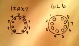
Okay I read something that you wrote that I would like to re-evaluate the voltages I posted. First, I want to make sure that I am reading the pins right. My schematic only shows where pin 1 on the 6L6 is, not for the 12AX7's, so I looked online for an image on where pin 1 is. I have the amp lying face down with the tube PCB facing me. I read all the values I posted on 1000DCV (high voltage) so that could be one factor altering the correct values. You posted vAC for R80 and R81, so I know I was wrong there. I will re-take those readings. On pin 8 (if the pins reading I have is indeed correct) did not give 46v, it flashed a -46 and would give a loud humming sound. But first things first, is this the right positions for the tube pins? And secondly, do I read the tube readings on my meter at 1000DCV (high voltage)? Thanks for clarifying this.
Attachments
Okay I read something that you wrote that I would like to re-evaluate the voltages I posted. First, I want to make sure that I am reading the pins right. My schematic only shows where pin 1 on the 6L6 is, not for the 12AX7's, so I looked online for an image on where pin 1 is. I have the amp lying face down with the tube PCB facing me. I read all the values I posted on 1000DCV (high voltage) so that could be one factor altering the correct values. You posted vAC for R80 and R81, so I know I was wrong there. I will re-take those readings. On pin 8 (if the pins reading I have is indeed correct) did not give 46v, it flashed a -46 and would give a loud humming sound. But first things first, is this the right positions for the tube pins? And secondly, do I read the tube readings on my meter at 1000DCV (high voltage)? Thanks for clarifying this.
The 12AX7 is correct, but he 6L6 isn't, all valve pins I've ever seen count clockwise.
Using the 1000V range is fine, but you can use lower ranges for lower voltages.
Thanks Nigel for clarifying where the pins are. Okay so this should be more accurate now that Nigel and Enzo cleared some things upas far as setting my meter and which are the correct pins.
CP11: 417 volts
CP12: 0
The reading of V4 and V5 are reading in order pin 3,4,5,8
V4: 381, 380, 48(with loud humming every time I touched it), 0
V5: 380, 380, 48(with loud humming every time I touched it), 0
I changed the meter to ACV to read R80 and R81. These values were:
R80: 2.9
R81: 2.9
On the other side of these were both at 0.
- Status
- Not open for further replies.
- Home
- Live Sound
- Instruments and Amps
- Hot Rod Deville filter capacitors