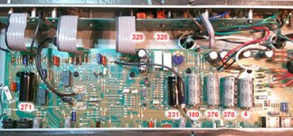
Here is what I'm faced with...originally I was getting a popping/crackling sound and my first impression was torn speaker. Attached to an external speaker and same thing, so then I thought tubes. Bought a new set of JJ's and installed. Same thing. I came across Justin Holton's site and did the test for the open R57 resistor. Test positive and while I was at it I noticed that the second filter cap (22uf 350volts) was leaky so decided to change that as well. According to Justin's advice he suggested to change out R4, R11, R16, R22, R57, and R58 for the plate loads. I ordered two new filter caps and the resistors (1/2w 82k for the R57 and 1/2w 100k for the rest). Installed everything and now no sound. All I get is a hum. I re-checked the solders and checked the voltage at R57 and all the filter caps. R57 is consistent on both sides now (329 and 328 respectively), but when I checked the filter caps I found a variance on the voltage. I have attached a pic showing the voltage I have at each along with the voltage at R57. Where should I go from here?
Attachments
well at least is marked like the same as the others (350V or 450V) so it's expected some high voltage in there
it's rated at 100uf with 350volts but when I have it running at is only putting out 4 volts. I noticed that the other one, third from the left is only putting out 180 volts so could this be going bad. I just changed out the first two from the left to right and but I wasn't sure if you change a filter cap out if you should just do all of them or just the ones that were leaky.
The cap is passive, it isn't putting out anything, the caps have voltage put across them by the rest of the circuit.
If a cap were so leaky as to drag your B+ down to 4v, I'd be expecting something to get real hot and likely fuses would blow. usually when caps fail they just stop functioning and the amp gets real hummy.
May I assume the voltages shown were taken at the other end of each cap rather than the end near the numbers?
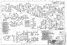
Look at your schematic. The 180v reading cap is C34, and is the bottom of two caps in series. Its upper partner is C33 to its right. They should have about the same voltage across each cap, and your 376 is ROUGHLY twice the 180. So call that OK. However, the pair of them ought to have more like 483v (and half that on the one).
The 4v cap on the end is C32. it is the bottom half of C31 and C32 series caps. They form the first filter node, often called the reservoir cap. C31 is the one next to it on left. With only 4v on C32, then that entire 378v is across the C31. That is not good for a 350v cap. And all that might explain why your voltage at C31 is only 378v instead of the 485v the schematic calls for.
We have a rule in our shop. FIX IT FIRST. Someone may suggest you "upgrade" some resistors or caps or whatever, and while it is tempting to make a lot of changes "while you are in there", in fact that is a bad idea. And this is exactly why. You used to have a working amp that made noise, now it makes no sound at all. The way to do it is to find and fix specifically what is wrong with it, and only THEN do we go back and change out parts we wish to upgrade or modify.
If a cap were so leaky as to drag your B+ down to 4v, I'd be expecting something to get real hot and likely fuses would blow. usually when caps fail they just stop functioning and the amp gets real hummy.
May I assume the voltages shown were taken at the other end of each cap rather than the end near the numbers?
Look at your schematic. The 180v reading cap is C34, and is the bottom of two caps in series. Its upper partner is C33 to its right. They should have about the same voltage across each cap, and your 376 is ROUGHLY twice the 180. So call that OK. However, the pair of them ought to have more like 483v (and half that on the one).
The 4v cap on the end is C32. it is the bottom half of C31 and C32 series caps. They form the first filter node, often called the reservoir cap. C31 is the one next to it on left. With only 4v on C32, then that entire 378v is across the C31. That is not good for a 350v cap. And all that might explain why your voltage at C31 is only 378v instead of the 485v the schematic calls for.
We have a rule in our shop. FIX IT FIRST. Someone may suggest you "upgrade" some resistors or caps or whatever, and while it is tempting to make a lot of changes "while you are in there", in fact that is a bad idea. And this is exactly why. You used to have a working amp that made noise, now it makes no sound at all. The way to do it is to find and fix specifically what is wrong with it, and only THEN do we go back and change out parts we wish to upgrade or modify.
Yes I checked the voltages from the positive side. So would you suggest that I reverse my process and recheck the resistors I changed since before it did make the crackling sound? R57 was internally not functioning though because it did only have voltage on one side and not the other. So for sure that was bad. And the leaky cap was C35. So I changed out C35 and C36. Would I check the resistor at R71 and R76? Assuming that the resistors I changed are ok?
R70/71 and R72/73 are balance resistors to ensure the voltage across those pairs of caps is evenly divided in two. Certainly we should check them, but they are not going to be "shorted." That doesn't mean there cannot be a solder bridge somewhere. We do need to solve the power suply issues before anything else is going to work right.
I have some nagging concerns, starting with R57. It is 82k. But you now have essentially the same voltage at both ends. That means no current is flowing through it. That could be the result of a number of things. R57,58 are the plate load resistors for V3, the phase inverter. That tube could have a bad side. Or the heater is not working on the one side of it. Or the socket could have lost its contact with a tube pin. If the voltage was taken right on the resistor leads, perhaps there is a break in the traces between the resistor and the tube socket or maybe a bad wire/connection in the ribbon cable. And since the part is a replacement, make sure it really is an 82k and not 82 ohms or 820 ohms. Believe me, not a season goes by that someone doesn't install a 470 ohm where a 470k belongs. If you had 300v on one end of R57 and zero on the other, then it would be open. Now we have voltage at both ends, so we know it is not openj, but we know little else about it.
I have some nagging concerns, starting with R57. It is 82k. But you now have essentially the same voltage at both ends. That means no current is flowing through it. That could be the result of a number of things. R57,58 are the plate load resistors for V3, the phase inverter. That tube could have a bad side. Or the heater is not working on the one side of it. Or the socket could have lost its contact with a tube pin. If the voltage was taken right on the resistor leads, perhaps there is a break in the traces between the resistor and the tube socket or maybe a bad wire/connection in the ribbon cable. And since the part is a replacement, make sure it really is an 82k and not 82 ohms or 820 ohms. Believe me, not a season goes by that someone doesn't install a 470 ohm where a 470k belongs. If you had 300v on one end of R57 and zero on the other, then it would be open. Now we have voltage at both ends, so we know it is not openj, but we know little else about it.
R70/71 and R72/73 are balance resistors to ensure the voltage across those pairs of caps is evenly divided in two. Certainly we should check them, but they are not going to be "shorted."
While not 'shorted', historically such resistors have been known to go VERY low value - essentially over-heated and going lower and lower resistance.
But in such cases it's usually pretty self evident by their colour.
As you say, same voltage either end of an 82K means no current flowing.
Way back at college, during a fault finding exam (where you weren't allowed access to the top of the board so couldn't visually find what had been done) one of the faults was an 'O/C' valve - not the heater, just not working at all. Easily found as long as the cathode has a resistor to chassis, so you can check anode, grid and cathode voltages.
What would a normal value range be for R57, R58. Going to check what you just mentioned and let you know if I find anything. Thanks.
Ok I checked each socket pin from the power tubes to the PCB and each pin has continuity. I did find that R70 loose and out of its point, so I did re-solder that and now C32 is reading somewhere around 182 volts, I didn't write it down, but it's getting current. I tried plugging in a guitar and still no sound. The set of 6L6's I have I'm there are new, but tried a different pair from another amp I have that I know is working, same result, no sound. I checked for any other loose things but did not see anything and tried wiggling with a wooden stick to see if anything else might be loose. Check continuity of ribbon cable and came out good. I tested all the resistors I replaced and they are correct. I'm not sure what else to try.
Oh sure, it is possible for R70-73 to go lower, but just in my experience with guitar amps, I'd have to put that in the horse/zebra thing and come up horse. (Old shop wisdom: when you see hoofprints in the dirt, think horses, not zebras made them.)
Space, you have a serious power supply issue. It may be something simple cdausing it, or maybe something strange, but I'd worry avout getting back the lost B+ voltage before I worried much further about R57.
But to answer your question, in a guitar amp, a good rule of thumb is about 1ma of current through a 12AX7 triode. Might be more, might be less, but that is a good enough expectation. Now 1ma of current through a 100k resistor, thanks to Ohm's Law, is 100v. SO if we connect a 100k resistor to 400v and draw 1,a through it, I'd expect about 100v to develop across the resistor. Meaning that I'd have 300v at the other end of that resistor. SO in your phase inverter, the B+ is supposed to be 441v, though yours is now much lower. So by my 1ma rule, I;d expect something like 331v on the plate at pin 6 through R58. And through 82k R57, I'd expect about 82v drop ss from 441, about 360. Those sound high to me, but the point if the test is not some precise voltage - this is only a guitar amp, not a science project - the point is we don;t want to see the full 441v on that plate, nor do we want to see zero. We want to see evidence of some reasonable current flow.
Your schematic doesn't specify plate voltages there, but it does show cathodes on the phase inverter tube as +42.8v. Call it 42v. The path through R55,56,68 is through: 470 ohms, 6.8k, and 4.7k, or 11,970 ohms. Remember that schematic voltages are average and not meant to be precise. SO I am going to call that 12k. 42v across 12k by Ohm's Law gives me about 3.5ma, which is 1.75ma per triode in that dual tube. Plug in those numbers, and we find 175v across a 100k and 144v across 82k. Drop those from the 441v and I might then expect 300v on pin 1 and on pin 6 maybe 266v. Remember, just ballpark. If I am within 40v either way of those, I'd call it close enough. Especially when the problem is "no sound." If it made plenty of sound but sounded bad, I might worry more closely, but we don;t get any sound.
Isolate the B+ problem.
Something is killing your B+. Try this: the primary center tap of your output transformer is a red wire on terminal post CP18. Disconnect that wire from the post, and see if the voltages on those main filter caps comes back up to close to the 440-485 the schematic calls for.
Ok I checked each socket pin from the power tubes to the PCB and each pin has continuity. I did find that R70 loose and out of its point, so I did re-solder that and now C32 is reading somewhere around 182 volts, I didn't write it down, but it's getting current. I tried plugging in a guitar and still no sound. The set of 6L6's I have I'm there are new, but tried a different pair from another amp I have that I know is working, same result, no sound. I checked for any other loose things but did not see anything and tried wiggling with a wooden stick to see if anything else might be loose. Check continuity of ribbon cable and came out good. I tested all the resistors I replaced and they are correct. I'm not sure what else to try.
First, those capacitors in you power supply should all be replaced. I have worked on several DeVilles and even own one. The only one that has not had a failure of one or more of those original Illinois power supply capacitors is the amp I personally own ( go figure). Now, once done, your voltages at the positive side of those capacitors should be over 200 volts on two with three above 400 volts (depending on your line voltage where you are using the amp). Check the plate voltages at each of the 12AX7's (pins 1 and 6 on each tube) If the plate voltages are there, I would suggest running a signal generator into the input, with all settings normal on the amp and just trace the circuit with an oscilloscope on the grids (pins 2 and 7 of each 12AX7) till you finally see where the signal is getting lost. That will narrow down the issues. As I said, these amps are known for having bad power supply capacitors. The oddest issue I ran into with bad power supply capacitors was a loss of volume when selecting any overdrive. When playing clean, the thing would work OK. I have run into other power supply related issues too. As they say, an amp is only as good as it's power supply.
I checked all the tubes and here is what I found at pins 1 and 6 respectively:
V1- 248, 248
V2- 248, 248
V3- 305, 305
V4- 0,0
V5- 0,0
R57- 305 on each side
R58- 305 on each side
It seems like no current is getting to V4 or V5.
V1- 248, 248
V2- 248, 248
V3- 305, 305
V4- 0,0
V5- 0,0
R57- 305 on each side
R58- 305 on each side
It seems like no current is getting to V4 or V5.
Hi Spacerust,
Did you cut the leads of the parts that have been replaced and soldered the new parts to these lead ends (parts side) or did you remove the pcb and soldered the new parts to the underside (track side) of the board?
If the first method (I personally find it a VERY bad one) then a solder blob or even a short can occure on the underside of the pcb.
I had a burned out Marschall coming in after a repair by someone else that way.
Check the underside of the pcb for:
- broken tracks due to overheating.
- Bad solderjoints
- shorts made with excess solder or leads from the parts sticking out to far.
Thank you Tarzan I will check it out when I get home this afternoon. I used a solder braid and took out the old resistors and any wires leaving just a clean hole in the pcb. I will double check for any excess solder and I even thought about unsoldering to check that the pcb was not overheated destroying the foil track. If the track is damaged (when I check) how would you reapair that to ensure the track has a solid pathway?
output valves
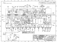
the output valves marked xv4 and xv5 on my schematic will not hav voltage on 1 and 6 as these are unused.
plate is on 3 and gets its voltage from the output transformer
grids 1 and 2 are on pins 4 and 5 these should hav power too.
if you havn't looked at those power supply faults you really should take care of that first.🙂
Attachments
- Status
- Not open for further replies.
- Home
- Live Sound
- Instruments and Amps
- Hot Rod Deville filter capacitors