Sometimes you fell like holding your head in your hands when you see something so stupid from a supposedly reputed maker.
I mean, how much extra a tapping at 15 to 18V on the 38V line, and a few extra vents would have cost during production?
I mean, how much extra a tapping at 15 to 18V on the 38V line, and a few extra vents would have cost during production?
Last edited:
It may be a good habit to see engineers, designers etc, as normal people with errors like everybody has. If they have a certain air on them you can simply ignore that. Many people play a role as uncertainty is common. There are several examples of designers/engineers that made design errors. There is 1 that even wanted extra money from clients to remedy the errors in his own design but even then he did not deliver. Brilliant designers also make a turd one day and should be told so, there is nothing wrong with being and staying a critical customer/technician. Keeps the quality level high. If the designer had to do costcutting it is the brand itself taking a shortcut.
Personality cult, brand loyalty (and refusing to see design defects) and blindly believing qualities of a certain brand or person ... not my cup of tea. We all make mistakes. Amateurs, DIYers, even laymen can find design errors and anyones comment should be taken seriously.
*IMHO the challenge in designing devices is to pose yourself the question "can I do it without ventilation slots?". So reduction of heat instead of allowing of heat and then trying to get rid of the already reduced amount of heat passively via scarcely ventilated (or even sealed) casing. Allowing fans in audio is simply a design weakness not a strength. Amplifiers with sealed casings can be done, there is one playing in the background 🙂
Last edited:

The device is what it is and the question is not about the competence of the manufacturer, but how to eliminate its error. First of all, replace thermal grease, drill openings in free places near radiators if possible. The author of the topic did not show the bottom of the apparatus, whether there are holes in the area of radiators. It will not help, put a small fan on reduced revolutions with the direction of air up.
Attachments
Last edited:
"The device is what it is". So the thread can be closed 😀
Keep the focus on "eliminating the error" though.
Keep the focus on "eliminating the error" though.
Last edited:
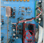
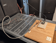
Here is the base plate of the NAD C320. There is big opening for the output stage, a grill for the power entry board, a grill under the main board driver area, and the rest is unvented. The main board mainly blocks air trying to rise from the base.
I am now preparing to do some temperature measurements under various operating conditions.

I am now preparing to do some temperature measurements under various operating conditions.
My understanding is that for ventilation to work properly the size of the escapes should be larger than that of the inputs.
If there is about 5mm space between the case and the circuit board I still think the problem is the lack of escape holes in the case top above those hot spots.
I'll check out my own NAD amps next time I am in the shed, perhaps mine have a similar problem.
It isn't a problem restricted to NAD.
I just had a local techie rebuild my Cambridge Audio Azure 840E with new bits [ relays etc] actually rated for the voltage supply inside the case, we drilled several holes in the bottom of the case to allow air in and used 5mm brass spacers at each screw point as an escape for hot air. Putting electronic components in an airtight case never made sense to me or to the techie who helped me with the project.
Yeah it is hard. If you don't have heat you don't need to get rid of it (also no ventilation needed). It is a novel concept 🙂 Another bonus is completely clean innards even after many years. They do it with electronic stuff for cars and industrially used switches, computers too. It works.Putting electronic components in an airtight case never made sense to me or to the techie who helped me with the project.
Fubar3, please measure transistors before and after ventilation mods and see the marginal difference as that casing already has ventilation slots. Bringing down dissipation ... ah well, forget it.
Last edited:
Yes jean-paul but in many of those applications the case itself is the heatsink, in my car the computer case is aluminium and very deeply finned and has channeled airflow from the radiator fan, here we are discussing possible retrofit cooling, and remediation are we not?
Perhaps replacing the hot/heat effected electrolytics with 105C rated caps is also the way to go?
I'm interested mainly because most of my own amps are old and during my last party the thermal protection circuits on a couple of my amps cut in and we were without music for a while, and when I say old I mean 1980s stuff.
I would be interested to know if your amps (or anyone's amps) have these vertical plates for heatsinks on PCBs. Please try the pinch test if and when you have time.I'll check out my own NAD amps next time I am in the shed, perhaps mine have a similar problem.
Gently pinch the plate between thumb and finger. Does the plate sting your finger?
I
Perhaps you mean 840W. As I read the detail, 840E is just the preamp which is hard to imagine as a source of significant heat. The user manual does emphasise care with its installation, location, free air flow etc. but that's probably a motherhood statement about hi-fi audio electronics in general.I just had a local techie rebuild my Cambridge Audio Azure 840E .......
Yes it is the Pre-Amp and it did get hot to touch, not OUCH hot but too warm to my way of thinking.
Not everybody plays music 8 to 10 hours a day but sometimes I do, it replaced my Yamaha C-80 which even after modification got too hot to touch in that scenario.
I do have adequate airflow etc:
Not everybody plays music 8 to 10 hours a day but sometimes I do, it replaced my Yamaha C-80 which even after modification got too hot to touch in that scenario.
I do have adequate airflow etc:
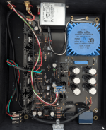
Ah, yes...seeing a few pics of the insides, I recall that the 840E and similar 800 series preamps, incorporate Douglas Self's multi-relay volume attenuator scheme instead of the usual, passive volume control pots. Nice idea Doug but keeping so many of those relays powered continuously with a clean, regulated supply, does generate extra heat and with apparently some 50+ signal relays inside, I guess the power consumption of the regulated supply and waste heat in the coils, adds up to quite a lot in use. The transformer and regulated power supply look to be huge indeed for a preamp but most of that would be associated with the necessary clean power supply to the relay coils.
Most pre amps are put UNDER the amp. so the convective aur to the amp is cooler.
If the pre amp is on top of the main amp, it is going to get warm air as the input.
And of space permits, use taller stand offs under the main PCB, so air flow is improved.
And you can always make holes in blank parts of the PCB.
If the pre amp is on top of the main amp, it is going to get warm air as the input.
And of space permits, use taller stand offs under the main PCB, so air flow is improved.
And you can always make holes in blank parts of the PCB.
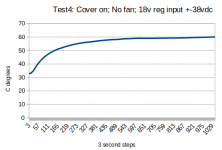
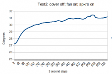
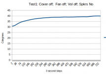
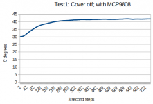
Did some temperature tests today of the NAD C320. Three of the tests stayed less than 40C which is a reasonable value which probably will not sting your fingers. However, test4 had my mods deactivated so that the behaviour is factory equivalent. It slowly climbed above 60C before I got tired waiting for stability. Perhaps thermal runaway would have occured if a butterfly flapped it's wings.
TestRig.png shows the temperature logging devices from Adafruit: Metro Mini 328 which is Arduino UNO equivalent. The 4-wire cable connects to MCP9808 accurate temperature sensor which is generic I2C. The temperature is measured every 3 seconds and logged in PC text file which is graphically displayed in a spreadsheet.
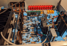
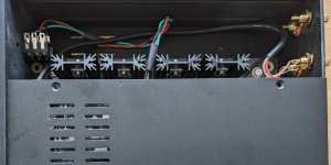
NAD-MCP9808.png shows the I2C cable entering via the output stage heatsink. The MCP9808 board is inserted into a groove of the +18vdc heatsink. It would be better if it was thermally bonded but this is good enough as is for comparative measurements.
The fan blows towards the 18v heatsinks. There is no input of external air so hot air just swirls around and lowers the temperature by spreading the heat. Some of it will find it's way to the vents.
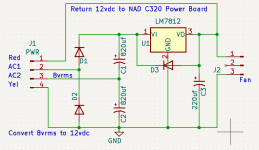
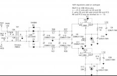
Fan-84vrms-12vdc.png is the voltage doubler which steals power from the rectifier board and shares the 12vdc needed by the fan. There is 16vdc created for the LM7812. The gridded PCB is clipped to the copper ground bar. Installation is not finished yet.
TestRig.png shows the temperature logging devices from Adafruit: Metro Mini 328 which is Arduino UNO equivalent. The 4-wire cable connects to MCP9808 accurate temperature sensor which is generic I2C. The temperature is measured every 3 seconds and logged in PC text file which is graphically displayed in a spreadsheet.
NAD-MCP9808.png shows the I2C cable entering via the output stage heatsink. The MCP9808 board is inserted into a groove of the +18vdc heatsink. It would be better if it was thermally bonded but this is good enough as is for comparative measurements.
The fan blows towards the 18v heatsinks. There is no input of external air so hot air just swirls around and lowers the temperature by spreading the heat. Some of it will find it's way to the vents.
Fan-84vrms-12vdc.png is the voltage doubler which steals power from the rectifier board and shares the 12vdc needed by the fan. There is 16vdc created for the LM7812. The gridded PCB is clipped to the copper ground bar. Installation is not finished yet.
Attachments

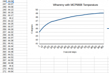
This post is for the Whammy HPA complete kit. It has regulator vertical heatsinks like the NAD 320 but fancier. It is Class A with the 7815 and 7915 each powering two mosfets. So the regulators power the hot spot in the Whammy. My build has the default settings. For example, the 7815 is lifted 2.1v by a LED which gives 17.1vdc output. There is 26.6vdc coming into the 7815 so it has a 9.1vdc drop. There is an option to restore the standard 15vdc but that would increase the heat generated by the 7815 so this option seems unwise.
The Whammy MCP9808 measures are fine at 40C with the cover removed. I recommend to operate it this way.
It took 50 minutes to reach 49C with the cover installed. I stopped logging but the temperature is still slowly rising. Now it is 49.7C or 121.5F. It's like baking a turkey.
...609, 50.01, 610, 50.02, 611, 50.02, 612, 50.02 ,613, 50.02, 614, 50.03 ...
And it just passed 50, the baking continues
Attachments
Last edited:
The Whammy is Class A with 60ma bias. So each regulator must provide 120+ ma. even when idle. The percent load does not matter since I am making comparative measures, not absolute value.What percent load?
What music?
The Whammy-reg image in the previous post has a 70053 xfmr with 2x15vac secondary. This unit is obsolete so 70064 comes with the kit. The kit unit has 2x18vac so there is more voltage to regulate.
Some Whammy HPA have different cases. The covers of the black case are only 25% vented, the vents are not aligned with the PCB heatsinks, so cooling is inefficient allowing temperature to rise for an hour or more of operation.
The Whammy is not vintage but it emulates the vintage NAD C320BEEE
Attachments
That obsolete Amveco 70053K is equal to the available Talema 70053K and they both even have the same typenumber. There is not more voltage to regulate when using a 2 x 18V transformer but there is more power to dissipate in useless heat. A challenge could be to use Schottky diodes and LT3045/LT3094 ultra low noise LDO regs with a 2 x 12V transformer to have +/-15V with a selected transformer. Maybe it would even work OK with a bog standard Talema 70052K as with 120 mA load it will give higher voltage than 2 x 12V ac. Challenging but interesting as load is constant with class A and ripple voltage is low with 120 mA so it either works with enough margin or it does not. Cleaner voltage, lower losses. I do so with a PSU and it measures fine, it has more than enough margin with a higher load current. It is cool too and it has only a few ventilation slots.
Bringing down the dissipated useless heat... Ah well, forget it. Bake that turkey 🙂
Bringing down the dissipated useless heat... Ah well, forget it. Bake that turkey 🙂
Last edited:
The Whammy build says that the bias can be reduced from 60ma to 40ma or 20ma. It lists the resistors to select but there is no explanation for why. I assume the lower bias is good enough for easy headphones. The regulator has a peculiar topology with common pin lifted by a LED-R-C circuit. The 7815 output should be 15vdc according to the schematic pin labels. I think the low power version would be better for me.That obsolete Amveco 70053K is equal to the available Talema 70053K and they both even have the same typenumber. ...
- Home
- Amplifiers
- Solid State
- Hot Heatsinks In Vintage Amps ... Such As NAD C320