
Basically, you're right. But this range also offers a few advantages. You can influence the height of the first resonance by experimenting with the length. And you can also use this range as an internal Helmholtz absorber (IHA) by introducing damping here. So there's definitely tuning potential here, allowing you to model your frequency response as desired. I've done this a few times with my TH projects.
Exactly. Just don't count it as path length. I agree it has a lot of function. Line it with absorbing material like wool or cotton fibre, Rockwool you can really attenuate the midrange. I have used this a number of times for different back loaded horn projects. The first one of these I made was of a plan that I really did not understand in 1994. I slowly learned about the useful benefits of this kind of chamber.Basically, you're right. But this range also offers a few advantages. You can influence the height of the first resonance by experimenting with the length. And you can also use this range as an internal Helmholtz absorber (IHA) by introducing damping here. So there's definitely tuning potential here, allowing you to model your frequency response as desired. I've done this a few times with my TH projects.
Moving the driver from the closed end of a horn/pipe doesn’t disconnect that section from it. It’s just an attempt to prevent the /3,9,15…. Resonace from being excited ?
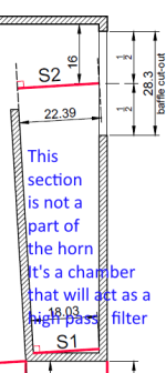
Thanks for your imput Mark.Careful what you consider a part of the horn length. The part below the driver entry hole is not a part of the horn path. It will act as filter in the horn path. Limiting the higher frequencies. Just as an inductor in a crossover limits high frequencies.
Well, this greatly changes the length of the tube. Although until now I've been almost mechanically integrating the feedback from those who have commented in order to feed the software with the appropriate data, I'd like to learn the theory behind it.
I did the graphic exercise based on what I understood from your suggestion. What's not clear to me is whether the determination of the areas of sections S1 through S5 should change with this new consideration, because these are the ones that volumetrically determine the folded horn (something like a folded Voigh pipe, which is what I understand), that is, width X height X (and)length.
Above is a sketch comparing what I had (C) and the new information (C'). This changes the data enormously.
Regards,
B.
It will do a few things. Yes, there will be a resonance excited. You can calculate that with the reflective path length of the bottom of the bucket, and the inside of the enclosure top. A secondary resonance will be left of the bucket to the inside of the front baffle. Many people never think about these things. But they are there. I spent months with one client chasing all of this stuff.Moving the driver from the closed end of a horn/pipe doesn’t disconnect that section from it. It’s just an attempt to prevent the /3,9,15…. Resonace from being excited ?
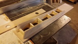
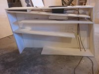
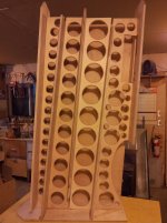
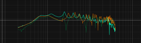
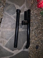
A few examples of how I have applied these principles. When I design ed these about 13 and 14 years ago I was not really thinking about using absorbing materials. Those epiphanies cam along later. These are back loaded horns. The smaller one with a bit of EQ is flat to 30 hertz. THe larger one we had flat to 14 hertz in a hotel room. Lets just say it was fun!Thanks for your input Mark.
Attachments

I messed around with it in an effort to find the velocity node for those resonances(and prevent them). I didn’t know if you could also use it to land on a (specific) pressure node and further excite them? I should mess around with thus more
Attachments
Last edited:
OK Mark. What I had read preliminary, in Martin J. King's papers, which summarize the determination of the line in outline, is that the entire length was considered. Of course, the confusion lies with the folded line versus the driver's position, which subdivides the direction, affecting "displacement, velocity, and acceleration" (I suppose).A few examples of how I have applied these principles. When I design ed these about 13 and 14 years ago I was not really thinking about using absorbing materials. Those epiphanies cam along later. These are back loaded horns. The smaller one with a bit of EQ is flat to 30 hertz. THe larger one we had flat to 14 hertz in a hotel room. Lets just say it was fun!
I drew the enclosure with the line without considering the chamber used as a filter, which greatly affects the length of the line. Could you comment? Thanks in advance.
It actually IS treated as part of the horn in an Offset-Driver Model in Hornresp. My BOXPLAN sims treat it the same way as well, and the measured results of my builds are a good match for the sims. Almost every build I've done is based on an offset-driver Hornresp model.Careful what you consider a part of the horn length. The part below the driver entry hole is not a part of the horn path. It will act as filter in the horn path. Limiting the higher frequencies. Just as an inductor in a crossover limits high frequencies.
It shouldn't change anything because it doesn't apply to your model. By indicating S2 as the location of the driver, what you are modeling is an OFFSET-DRIVER design, and in such a design the path DOES start at S1!Thanks for your imput Mark.
Well, this greatly changes the length of the tube. Although until now I've been almost mechanically integrating the feedback from those who have commented in order to feed the software with the appropriate data, I'd like to learn the theory behind it.
I did the graphic exercise based on what I understood from your suggestion. What's not clear to me is whether the determination of the areas of sections S1 through S5 should change with this new consideration, because these are the ones that volumetrically determine the folded horn (something like a folded Voigh pipe, which is what I understand), that is, width X height X (and)length.
View attachment 1441315
Above is a sketch comparing what I had (C) and the new information (C'). This changes the data enormously.
Regards,
B.
If instead you were modeling this as if S1 was the location of the driver, then yes, that space below the driver should be considered as a chamber in Hornresp, but as Hornresp does not provide a means of modeling that chamber as tapered, so don't do that, LOL.
I missed that detail Brian! Perfect. So the sims are correct. The absorption advice still applies. So does the chamber characterization. So many things with Hornresp are out of my normal usage. I need to pay better attention to the posts!By indicating S2 as the location of the driver, what you are modeling is an OFFSET-DRIVER design, and in such a design the path DOES start at S1!
Thanks for the help @Brian Steele. By the way, now that I've been revisiting the Martin J. King papers I reviewed a few months ago, to see if I could make any sense of what Mark was telling me, I came across the methods for determining line centering again.Option C is the way to go, and it will be the closest match to the Hornresp data for the sim.
my investigation pointed the root cause
Hi Marcelo,
Well done on identifying what was causing the problem - excellent detective work on your part 🙂.
If instead you were modeling this as if S1 was the location of the driver, then yes, that space below the driver should be considered as a chamber in Hornresp, but as Hornresp does not provide a means of modeling that chamber as tapered, so don't do that, LOL.
It can be modelled using the SH1 loudspeaker configuration option. The results for the following two systems are identical.
OD:
SH1:
COMPARISON:
excellent detective work
Well, Sherlock Holmes was a classic British detective that influenced many generations worldwide. I'm probably one of them. 🧐
When I open hornresp it tells me there's a new version. I download, unzip, open the program back up, and it tells me that there's still a new version. What am I doing wrong?
It seems that the new version is being stored in a different folder to the old version so that the old version is not automatically overwritten and is still being used. Try deleting all instances of the existing version before downloading the new version and make sure the new version is stored in the recommended C:\Hornresp folder. Check that the Product Number of your latest version is 5730-250328 (the Product Number can be found under the Help > About Hornresp menu).
That did it. Tyvm 🙂It seems that the new version is being stored in a different folder to the old version so that the old version is not automatically overwritten and is still being used. Try deleting all instances of the existing version before downloading the new version and make sure the new version is stored in the recommended C:\Hornresp folder. Check that the Product Number of your latest version is 5730-250328 (the Product Number can be found under the Help > About Hornresp menu).
Hornresp Update 5730-250410
Hi Everyone,
BUG FIX
A minor bug in the code that generates the loudspeaker wizard Schematic and System Model diagrams has now been fixed. It was introduced with the release of Version 57.30. The accuracy of the simulation results was not affected.
Kind regards,
David
Hi Everyone,
BUG FIX
A minor bug in the code that generates the loudspeaker wizard Schematic and System Model diagrams has now been fixed. It was introduced with the release of Version 57.30. The accuracy of the simulation results was not affected.
Kind regards,
David
- Home
- Loudspeakers
- Subwoofers
- Hornresp