No. Any added resistance should be added to Rg, not Re.
Because TS parameters is relying on Re when calculated.
While you could argue that the result is the same (or at least appears so in the SPL plot) for a single driver, adding a second one will give a wrong result.
And if you recalculate any value after Re they will change to a wrong value as well.
Not to mention the Pe calculation and electrical impedance will be wrong.
I never thought about multiple drivers. Good point David.
Hard to argue when you make sense.
Most inductors will not add that much resistance in a single sample but multiplied they will run everything off the rails.
Mark
Hard to argue when you make sense.
Most inductors will not add that much resistance in a single sample but multiplied they will run everything off the rails.
Mark
yes and the cables too.Gentlemen
Simple question?
When adding an inductor to a tapped horn sim, should I add the resistance of the inductor to the Re value, in the same way that I add the inductance to the Le?
Thanks in advance
Martin
Gentlemen
Simple question?
When adding an inductor to a tapped horn sim, should I add the resistance of the inductor to the Re value, in the same way that I add the inductance to the Le?
Thanks in advance
Martin
Hi,
Agree with David here-above,
Yes, that procedure would work but its not a good practice because the fundamental T/S would be affected too, i.e. Qes would be more lossy and Qts will thus alter if pressing Sd at the HR main input screen.
IMO: More convenient is to add the inductor resistance to Rg.
b
Thanks for all the replies!😱
I will add the inductor (and cable) resistance to Rg
and the inductance to the Le value 🙂
I will add the inductor (and cable) resistance to Rg
and the inductance to the Le value 🙂
Hi David_Web, Mark and Oliver,
Thanks for your feedback on the slider operation. After giving it much consideration I have decided to leave things as they are, at least for the time being.
I have found that the new system is not too bad once you get used to it, particularly if the slider values are set by clicking rather than dragging, and the sensitivity is managed dynamically using the Spacebar key.
The same slider operation is now used for all loudspeaker types. Previously the tapped horn system was different to the others.
The auto / manual settings will continue to default to manual once the Loudspeaker Wizard is closed.
Kind regards,
David
Auto v. Manual
Hi David,
I vote for manual over automatic as a default. (I know I don't have a vote, but I can keep on dreaming, can't I?)
Thanks for the latest greatest, it works for me.
Regards,
Hi David,
I vote for manual over automatic as a default. (I know I don't have a vote, but I can keep on dreaming, can't I?)
Thanks for the latest greatest, it works for me.
Regards,
Could we at least get the auto/manual toggle buttons on the first page so we don't have to switch pages back and forth every time the wizard is to be used?
hi david friend
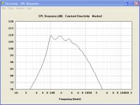
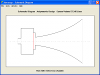
try to sim FLH likes the pic i post above. david friend i want to ask that if the resp freq has a ripple -+ not over than 5 db, i want to know it can work fine. and another one question i see the the F horn on this pic. i'll try to sim and use the OD option. is it all right./🙂
try to sim FLH likes the pic i post above. david friend i want to ask that if the resp freq has a ripple -+ not over than 5 db, i want to know it can work fine. and another one question i see the the F horn on this pic. i'll try to sim and use the OD option. is it all right./🙂
Attachments

Could we at least get the auto/manual toggle buttons on the first page so we don't have to switch pages back and forth every time the wizard is to be used?
Hi David_Web,
I would prefer not to have the S2 and S4 sliders of a four-segment tapped horn on the first page of the Loudspeaker Wizard, and I don't want to separate the toggle buttons away from the sliders.
When I get a chance I will see what can be done to address your concerns though - possibly by saving the auto / manual settings as part of the permanent record (provided that this does not lead to other problems). This is what you were requesting earlier, I believe.
Kind regards,
David
Last edited:
Hi Thawach,
That is really something for you to decide, although +/- 3dB should be okay, I expect.
Assuming that I have interpreted the drawing correctly, I think I would probably simulate the design as a horn with a vented rear chamber, rather than as an offset driver horn.
Kind regards,
David
i want to know it can work fine.
That is really something for you to decide, although +/- 3dB should be okay, I expect.
i see the the F horn on this pic. i'll try to sim and use the OD option. is it all right.
Assuming that I have interpreted the drawing correctly, I think I would probably simulate the design as a horn with a vented rear chamber, rather than as an offset driver horn.
Kind regards,
David
Attachments
Last edited:
thanks a lot david for this answer. at first i worry about transient respond. my model i want the short horn because this it's difficult to get flat respond freq. david i design again. it has problem a little. ok 1 watt is near to flat. but when i sim the high spl. it make me surprise that when i sim over than 70 watts. i see the voice coil is xceed. the woffer only has the x max 3 mm. but when i see the spec from manufacture. they has the handing power 200-300 watts. i'm surprise really. but does not matter. i 'll use this model. david most of people in thailand can't use this program. they know this is the best software. they would like to use for Pa. sorry they didn't know how to? yesterday i told on thai website. david reply to me is the best. ok david i'll use this software to sim the model and helps people who still have difficult life in thailand to make money for their life.
love,love friend🙂
love,love friend🙂
Attachments
David, is there any chance you possibly expand capabilities of Hornresp to make it a simulation tool for "Deep Frame Dipole" speakers ?
my new "baby" :
http://www.diyaudio.com/forums/subwoofers/172553-amt-sub-using-dynamic-woofer.html#post2394757
What would be needed is a possibility to simulate a *distributed speakers arrangement* in pipes - and possibly add dipole behavior as you already do with compound horns.
Pipes of course should be free in shape (within the limits you already provide for horns, but at least conical and cylindrical) and multiple placement of chassis should be possible everywhere along the pipe depth.
The mores speakers you can allow to be placed in the DFD pipe the better (two will do fine for a starter)...
🙂
Michael
most of people in thailand can't use this program.
Hi Thawach,
The P.Audio System Company in Thailand has been known to use Hornresp 🙂.
Good luck with your design.
Kind regards,
David
David, is there any chance you possibly expand capabilities of Hornresp to make it a simulation tool for "Deep Frame Dipole" speakers ?
Hi Michael,
It's highly unlikely. Maybe AkAbak could be used instead?
Kind regards,
David
I vote for manual over automatic as a default.
Hi Oliver,
You can rest easy - the default will remain as "manual", no matter what else might change 🙂.
Otherwise, the original manual values of S2 and S3 / S4 on main input screen would be not be copied into the Wizard.
Kind regards,
David
Manual v. Automatic
Hi David,
That is exactly what was happening to me before, I would make changes in the input window, e.g.: to S1 or S5, and when I entered the Wizard there would an automatic adjustment to S2 or S4. I like it better this way.
Thanks, Regards,
Hi David,
That is exactly what was happening to me before, I would make changes in the input window, e.g.: to S1 or S5, and when I entered the Wizard there would an automatic adjustment to S2 or S4. I like it better this way.
Thanks, Regards,
Hi Michael,
It's highly unlikely. Maybe AkAbak could be used instead?
Kind regards,
David
🙁
- Home
- Loudspeakers
- Subwoofers
- Hornresp