Sorry for the long reply. David, what I am asking about with the inputs is to calculate the angle of each segment. I'm trying to import it into CAD software. (Any with a free demo or that is free so I can fold it and build it.) I think that knowing the width, height and depth of each section, and then angle of the curve is the easiest way to do it, and then with AutoCAD's math function draw it out. But I don't know.
Last edited:
So ideally four drivers (two series strings wired in parallel) should gain around 6dB in efficiency correct?
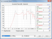
It is not quite as simple as that. Try comparing the Hornresp acoustical power responses for Nd = 1 and Nd = 2P 2S to see how the difference between the two sets of results varies across the frequency range, for the speaker design you have in mind.
I presume arranging 4 drivers in a square pattern would couple better than 4 in a line.
Theoretically, yes. The closer together all the drivers are, the better the bass performance.
In practice is there a significant difference in the two layouts?
I am not qualified to answer this question - I have no practical experience in such matters 🙂.
what I am asking about with the inputs is to calculate the angle of each segment.
Hi StainlessSteve,
As far as calculating the angle of each segment is concerned, using the data from the first three lines of your exported schematic to illustrate:
Length (cm) Area (sq cm) Side Len (cm) Height/2 (cm) Top Len (cm) Width/2 (cm) Width Flare
0.000000 108.800000 0.000000 1.133333 0.000000 24.000000 Con
6.000000 138.605000 6.000000 1.443802 6.008027 24.000000 Con
12.000000 168.410000 12.000000 1.754271 12.016054 24.000000 Con[/QUOTE]
Segment 1 horizontal included angle = 2 * Arctan((1.443802 - 1.133333) / (6.000000 - 0.000000))
Segment 2 horizontal included angle = 2 * Arctan((1.754271 - 1.443802) / (12.000000 - 6.000000))
Or:
Segment 1 horizontal included angle = 5.92 degrees
Segment 2 horizontal included angle = 5.92 degrees
Kind regards,
David
I presume arranging 4 drivers in a square pattern would couple better than 4 in a line. In practice is there a significant difference in the two layouts?
Yes and no, the line array will have a lower horizontal coupling BW [wider polar pattern], but a higher vertical one [narrower polar pattern], whereas the square one will be ~ uniformly square to start with, so ~the same on average, just the polar patterns [acoustic power responses] will be considerably different and why there's so many different horn configurations to cover as many as practical patterns typically seen in the various in/out door apps.
As frequency increases though, both collapse based on a 10^6/[wall angle*mouth width] rule-of-thumb or in the case of point source drivers a piston response calculator gives good enough data to either plot it or draw overlapping rings to scale to better see how the pattern collapses over distance/time.
Note that non round shaped patterns will maintain them over quite long distances, not collapse to ~round with increasing distance, frequency as some believe/assume. When we tested a large, long range annunciation horn array its pattern was still close enough intact to meet the client's stringent 1/2 mi./100 dB spec through/over a mildly dense forest at up to 65? mph winds [facility on a small, remote mountain top].
GM
how might hornresp be set to accurately simulate G.A. Brigg's cabinets which had ~2:1 chamber ratio and 1/16" wide slits in what he termed an "acoustic filter" ? Those cabinets were in normal squat aspect besides the column example below.
There had to be a fair amount of "drag" from 1/6" wide slits in a half inch thick partition board. I had the idea the filter's function partly was to reduce excursion in the record warp region (?)
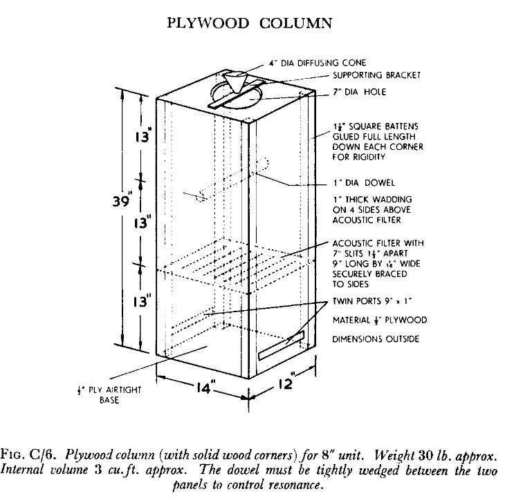
There had to be a fair amount of "drag" from 1/6" wide slits in a half inch thick partition board. I had the idea the filter's function partly was to reduce excursion in the record warp region (?)
how might hornresp be set to accurately simulate G.A. Brigg's cabinets which had ~2:1 chamber ratio and 1/16" wide slits in what he termed an "acoustic filter" ?
Hi freddi,
The "acoustic filter" shown in your diagram is actually an acoustical resistance. This can be readily specified in AkAbak using the AcouResistance element, but with Hornresp, the closest that you can get is to specify acoustical absorbent material instead.
The general layout would be as shown in Attachment 1 (not to scale). The effect of adding the "acoustic filter" component can be seen in Attachments 2 and 3.
Kind regards,
David
Attachments


Hornresp Update 4810-180907
Hi Everyone,
CHANGE 1
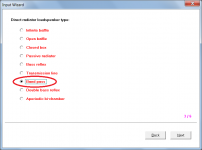
Double bass reflex (DBR) enclosures can now be directly specified. Post #8579 and Attachments 1 and 2 refer.
CHANGE 2
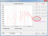
The Include Gain feature, enabling room or cabin gain to be imported and taken into account in the power response chart, has now been added to the BP4, BP6 (series), BP6 (parallel), BP8, DBR and ABC loudspeaker wizards. Attachment 3 refers.
CHANGE 3
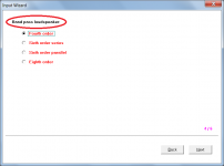
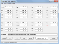
Band pass enclosure loudspeakers now have their own options group in the Input Wizard. Attachments 4 and 5 refer.
BUG FIX
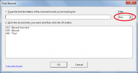
The 'Bes' Bessel horn option had not been included in the Find tool filter. This has now been fixed. Attachment 6 refers.
Kind regards,
David
Hi Everyone,
CHANGE 1
Double bass reflex (DBR) enclosures can now be directly specified. Post #8579 and Attachments 1 and 2 refer.
CHANGE 2
The Include Gain feature, enabling room or cabin gain to be imported and taken into account in the power response chart, has now been added to the BP4, BP6 (series), BP6 (parallel), BP8, DBR and ABC loudspeaker wizards. Attachment 3 refers.
CHANGE 3
Band pass enclosure loudspeakers now have their own options group in the Input Wizard. Attachments 4 and 5 refer.
BUG FIX
The 'Bes' Bessel horn option had not been included in the Find tool filter. This has now been fixed. Attachment 6 refers.
Kind regards,
David
Attachments

the closest that you can get is to specify acoustical absorbent material instead.
Just to clarify - the acoustical absorbent material is of course porous.
David, maybe I have already wished for this?
I would like to be able to calculate pressure on the diaphragm. Increasing the Vtc should lower the pressure on the diaphragm I believe. But I would like to know 🙂
Edit:
I have simulated this in my current design using two extra segments. Increasing the front chamber from small to very large increases the pressure.
How much pressure can a diaphragm take? I know it varies, but a rule of thumb would be great.
Thanks David!
Mårten
Last edited:
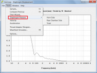
Hi Mårten,
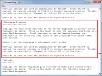
Select Tools > Diaphragm Pressure from the Diaphragm Displacement chart.
I am not aware of a rule of thumb. Perhaps someone else may know...
Kind regards,
David
I would like to be able to calculate pressure on the diaphragm.
Select Tools > Diaphragm Pressure from the Diaphragm Displacement chart.
How much pressure can a diaphragm take? I know it varies, but a rule of thumb would be great.
I am not aware of a rule of thumb. Perhaps someone else may know...
Kind regards,
David
Attachments
another on the "wish-list" - a "scaling" factor to scale (just) the enclosure input to see how a design might fare scaled up or down in percent - then the result would be easy to add and check with appropriate larger/smaller drivers. Could that be done without messing up things and enormous time in modifying hornresp? Would it cause too much confusion? I know its only practical to some point where 1/4 wave path dominates but could save time vs using a calculator.
- Home
- Loudspeakers
- Subwoofers
- Hornresp