THis I never found in the manual!
Hi Mark,
Have a look at the first item on page 7 of the Hornresp Help file.
Kind regards,
David
What I wouldn't mind seeing though is the 'find' option in all windows instead of just the 'input' if it's quick/easy to do.
Hi GM,
While it would not be difficult to do, my preference is that the user returns to the main input screen to access the Find tool. To me, the operation seems a bit more logical that way. To quickly return to the input parameters window from any other window simply press the Esc key on the keyboard.
Kind regards,
David
Generated impulse disagrees with hornresps SPL. But which is really accurate?
I just tried this with a TH I'm fiddling with and got a similar result.
Hi David_Web and fb,
In theory, the SPL response predicted directly by Hornresp should be more accurate than the SPL response calculated by HOLMImpulse using derived impulse response data imported from Hornresp. The method used by Hornresp to calculate impulse response was developed by Jean-Michel Le Cléac'h. He would be the person best qualified to comment on the reasons for the differences you are seeing.
Jean-Michel, if you read this, you might like comment - thanks.
Kind regards,
David
Hornresp Version 23.20
Hi Oliver,
While working through the code to locate the bugs you found in the compound horn combined response model, I realised that I could further refine the algorithms so that the SPL and impulse response results produced when a non-zero path length difference was specified, would be more accurate.
This improvement has now been implemented in Hornresp Version 23.20.
You may find the results of the following "sanity check" exercise of some interest. I used your "original" compound horn configuration but with Lrc changed from 7 cm to 8 cm as explained in Post # 734.
TEST 1. WITH 0 CM PATH LENGTH DIFFERENCE:
Path length from the front side of the diaphragm to the 1 metre reference measurement point:
Ltc + L12 + 100 = 600 / 300 + 41 + 100 = 143 cm
Front path time delay = 143 / 34400 x 1000 = 4.16 msec
Path length from the rear side of the diaphragm to the 1 metre reference measurement point:
Lrc + L56 + 100 = 8 + 336 + 100 = 444 cm
Rear path time delay = 444 / 34400 x 1000 = 12.91 msec
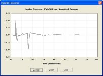
See Test1.jpg attached. The positive (front) spike is located at 4.16 msec and the negative (rear) spike is located at 12.91 msec, consistent with the calculated results above. Even though the mouth of the rear horn is the same distance from the measurement point as the mouth of the front horn, the normalised amplitude of the negative (rear) spike is greater than the normalised amplitude of the positive (front) spike because the rear horn is more efficient at lower frequencies than the front horn.
TEST 2. WITH 90 CM PATH LENGTH DIFFERENCE:
Path length from the front side of the diaphragm to the 1 metre reference measurement point:
Ltc + L12 + 100 = 600 / 300 + 41 + 100 = 143 cm
Front path time delay = 143 / 34400 x 1000 = 4.16 msec
Path length from the rear side of the diaphragm to the 1 metre reference measurement point:
Lrc + L56 + Diff + 100 = 8 + 336 + 90 + 100 = 534 cm
Rear path time delay = 534 / 34400 x 1000 = 15.52 msec
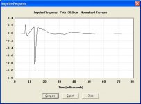
See Test2.jpg attached. The positive (front) spike is located at 4.16 msec and the negative (rear) spike is located at 15.52 msec, consistent with the calculated results above. Even though the mouth of the rear horn is 90 cm further away from the reference measurement point than the mouth of the front horn, the normalised amplitude of the negative (rear) spike is only slightly less than the normalised amplitude of the positive (front) spike because the rear horn is more efficient at lower frequencies than the front horn.
TEST 3. WITH -90 CM PATH LENGTH DIFFERENCE:
Path length from the front side of the diaphragm to the 1 metre reference measurement point:
Ltc + L12 - Diff + 100 = 600 / 300 + 41 + 90 + 100 = 233 cm
Front path time delay = 233 / 34400 x 1000 = 6.77 msec
Path length from the rear side of the diaphragm to the 1 metre reference measurement point:
Lrc + L56 + 100 = 8 + 336 + 100 = 444 cm
Rear path time delay = 444 / 34400 x 1000 = 12.91 msec
See Test3.jpg attached. The positive (front) spike is located at 6.77 msec and the negative (rear) spike is located at 12.91 msec, consistent with the calculated results above. Because the mouth of the rear horn is 90 cm closer to the measurement point than the mouth of the front horn, and because the rear horn is more efficient at lower frequencies than the front horn, the normalised amplitude of the negative (rear) spike is considerably greater than the normalised amplitude of the positive (front) spike.
Kind regards,
David
I downloaded and installed V2310-090925 and everything looks fine.
Hi Oliver,
While working through the code to locate the bugs you found in the compound horn combined response model, I realised that I could further refine the algorithms so that the SPL and impulse response results produced when a non-zero path length difference was specified, would be more accurate.
This improvement has now been implemented in Hornresp Version 23.20.
You may find the results of the following "sanity check" exercise of some interest. I used your "original" compound horn configuration but with Lrc changed from 7 cm to 8 cm as explained in Post # 734.
TEST 1. WITH 0 CM PATH LENGTH DIFFERENCE:
Path length from the front side of the diaphragm to the 1 metre reference measurement point:
Ltc + L12 + 100 = 600 / 300 + 41 + 100 = 143 cm
Front path time delay = 143 / 34400 x 1000 = 4.16 msec
Path length from the rear side of the diaphragm to the 1 metre reference measurement point:
Lrc + L56 + 100 = 8 + 336 + 100 = 444 cm
Rear path time delay = 444 / 34400 x 1000 = 12.91 msec
See Test1.jpg attached. The positive (front) spike is located at 4.16 msec and the negative (rear) spike is located at 12.91 msec, consistent with the calculated results above. Even though the mouth of the rear horn is the same distance from the measurement point as the mouth of the front horn, the normalised amplitude of the negative (rear) spike is greater than the normalised amplitude of the positive (front) spike because the rear horn is more efficient at lower frequencies than the front horn.
TEST 2. WITH 90 CM PATH LENGTH DIFFERENCE:
Path length from the front side of the diaphragm to the 1 metre reference measurement point:
Ltc + L12 + 100 = 600 / 300 + 41 + 100 = 143 cm
Front path time delay = 143 / 34400 x 1000 = 4.16 msec
Path length from the rear side of the diaphragm to the 1 metre reference measurement point:
Lrc + L56 + Diff + 100 = 8 + 336 + 90 + 100 = 534 cm
Rear path time delay = 534 / 34400 x 1000 = 15.52 msec
See Test2.jpg attached. The positive (front) spike is located at 4.16 msec and the negative (rear) spike is located at 15.52 msec, consistent with the calculated results above. Even though the mouth of the rear horn is 90 cm further away from the reference measurement point than the mouth of the front horn, the normalised amplitude of the negative (rear) spike is only slightly less than the normalised amplitude of the positive (front) spike because the rear horn is more efficient at lower frequencies than the front horn.
TEST 3. WITH -90 CM PATH LENGTH DIFFERENCE:
Path length from the front side of the diaphragm to the 1 metre reference measurement point:
Ltc + L12 - Diff + 100 = 600 / 300 + 41 + 90 + 100 = 233 cm
Front path time delay = 233 / 34400 x 1000 = 6.77 msec
Path length from the rear side of the diaphragm to the 1 metre reference measurement point:
Lrc + L56 + 100 = 8 + 336 + 100 = 444 cm
Rear path time delay = 444 / 34400 x 1000 = 12.91 msec
See Test3.jpg attached. The positive (front) spike is located at 6.77 msec and the negative (rear) spike is located at 12.91 msec, consistent with the calculated results above. Because the mouth of the rear horn is 90 cm closer to the measurement point than the mouth of the front horn, and because the rear horn is more efficient at lower frequencies than the front horn, the normalised amplitude of the negative (rear) spike is considerably greater than the normalised amplitude of the positive (front) spike.
Kind regards,
David
Attachments

Last edited:
This improvement has now been implemented in Hornresp Version 23.20.
Hi Oliver,
Just letting you know that I have released a minor update to correct a problem that could sometimes occur when the Sample tool was used on a combined response with a non-zero path length difference. Product Number 2320-090928 refers.
Also, out of curiosity I conducted another impulse response validation check using a compound horn with identical front and rear 244 cm long horns, but without chambers. The total path length to the 1 metre reference measurement point for each horn is 344 cm, giving an overall path delay of 10 msec.
TEST 1. WITH 0 CM PATH LENGTH DIFFERENCE:
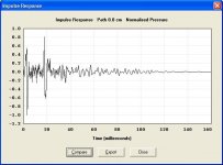
For a 0 cm path length difference, the pulses from the front and rear sides of the diaphragm will arrive at the reference measurement point after 10 msec, 180 degrees out of phase. Theoretically this should result in total cancellation of the two pulses.
Looking at Test1.jpg attached, you will see that there is no noticeable pulse at 10 msec, which is consistent with the theory. The "ringing" shown across the time scale is simply an artefact of the impulse response calculation process. It is actually very low level noise, only made apparent in this case because the maximum value, although extremely small, has been normalised to 1.
TEST 2. WITH 172 CM PATH LENGTH DIFFERENCE:
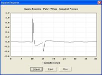
For a 172 cm path length difference, the pulse from the front side of the diaphragm will arrive at the reference measurement point after 10 msec, and the pulse from the rear side of the diaphragm will arrive 5 msec later, opposite in phase.
Looking at Test2.jpg attached, you will see that this is in fact the case. You will also note that the low level ringing noise artefact is no longer evident because the maximum value now normalised to 1 is the amplitude of the pulse from the front side of the diaphragm. The absolute amplitude of the rear pulse is less than 1 because the mouth of the rear horn is 172 cm further away from the reference point than the mouth of the front horn.
Kind regards,
David
Attachments
Hello David,
Such differences as noticed by David_Web happens in the case of long and resonant horns having a pulse response made of a lot of reflections.
Let's remember that the pulse exported by Hornresp is only 20001 samples long at a 48kHz sampling frequency.
With most horns, only one half of the window is used (the origin of time being at sample 10001 and "negative time" only happening in the case of "combined response")
10000 sample at 48kHz is (nearly) equivalent to 0,21 seconds and to 7,2 meters travelled at the speed of sound.
Then about the problem one can see below 100Hz with long and resonant horns (as all TQWT are): let's imagine a single conical horn 3 meters long (with a low frequency cut-off), the direct wave travels 3meters, the fist reflected wave travels 9meters, the second reflected wave travels 15meters, the third reflected wave travels 21meters.
For a good reproducing of the pulse response of such horn we can imagine that at least 2 or 3 reflections should be taken in account.
But now there is a reality: given the window width used in Hornresp and if we take the direct wave arrival as origin of time within the pulse window, only the first reflection will be reproduced.
In order to improve the pulse response in the case of long TH, then the width of the window for the pulse response should be increased by a factor 2 or 3 and then the duration of the calculation of the pulse will be quite long.
It is possible but is it worth the work?
Best regards from Paris, France
Jean-Michel Le Cléac'h
Hi David_Web and fb,
In theory, the SPL response predicted directly by Hornresp should be more accurate than the SPL response calculated by HOLMImpulse using derived impulse response data imported from Hornresp. The method used by Hornresp to calculate impulse response was developed by Jean-Michel Le Cléac'h. He would be the person best qualified to comment on the reasons for the differences you are seeing.
Jean-Michel, if you read this, you might like comment - thanks.
Kind regards,
David
Post #744 and #745:
Hi David,
Thank you for the extended explanations. This is very helpful, I'm understanding the impulse response plots a lot better now. I'll have to make more time to experiment with compound horn simulations, and particularly the impulse response.
Thanks for the additional update too (V2320-090928), haven't found any new ponderables yet 🙂.
Regards,
In order to improve the pulse response in the case of long TH, then the width of the window for the pulse response should be increased by a factor 2 or 3 and then the duration of the calculation of the pulse will be quite long.
It is possible but is it worth the work?
Hi Jean-Michel,
Many thanks for the detailed explanation. I am totally happy with the impulse response results currently being achieved by Hornresp - the test examples included in my earlier posts show that your method works very well indeed.
If you like though, I could see how much longer the calculations would take if the window width was increased by a factor of 2 or 3, as you have mentioned. I would need appropriately modified Matlab code to be provided by you first, however 🙂.
Perhaps the window width used for a specific calculation could be automatically selected based on the length and type of horn system being considered? Would this be a practical compromise?
Thanks and kind regards,
David
Thanks for the additional update too (V2320-090928), haven't found any new ponderables yet 🙂.
Hi Oliver,
I managed to find a very minor one - it has now been fixed in Product Number 2320-090929 🙂.
Kind regards,
David
Hello David,
Probably someone may imagine that the problem of using a larger time window for the pulse response is Hornresp is very trivial but it is not. The variable width windowing used for every frequency component is only optimized for the actual length of the time window.
Optimization of the windowing for a new fixed length of the time window will take some time but much more time is needed in the case of an adaptative length of the time window.
I can study this problem but surely it will take some time...
Best regards from Paris, France
Jean-Michel Le Cléac'h
Hi Jean-Michel,
Many thanks for the detailed explanation. I am totally happy with the impulse response results currently being achieved by Hornresp - the test examples included in my earlier posts show that your method works very well indeed.
If you like though, I could see how much longer the calculations would take if the window width was increased by a factor of 2 or 3, as you have mentioned. I would need appropriately modified Matlab code to be provided by you first, however 🙂.
Perhaps the window width used for a specific calculation could be automatically selected based on the length and type of horn system being considered? Would this be a practical compromise?
Thanks and kind regards,
David
Post #749 - #750
Hi David,
Just tried a few old simulations with your latest version (V2320-090929), and it all seems to work fine. Thanks again.
I'd also like to thank Jean-Michel for his work with the impulse response data. Thanks.
Regards,
Hi David,
Just tried a few old simulations with your latest version (V2320-090929), and it all seems to work fine. Thanks again.
I'd also like to thank Jean-Michel for his work with the impulse response data. Thanks.
Regards,
I can study this problem but surely it will take some time...
Hi Jean-Michel,
As you say, it is probably not really worth the effort. As indicated previously, I am very pleased with the way that the current impulse response algorithm operates. In the circumstances, can I suggest that we leave things just as they are, and save ourselves the extra work 🙂.
Thanks again for all your help.
Kind regards,
David
Just tried a few old simulations with your latest version (V2320-090929), and it all seems to work fine.
Hi Oliver,
Excellent 🙂.
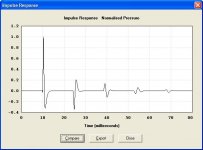
Just to illustrate Jean-Michel’s point regarding reflected waves, for a thin cylindrical horn having a length of 244 cm, impulses can be seen at:
(1 x 244 + 100) / 34400 x 1000 = 10.00 msec (+ve phase)
(3 x 244 + 100) / 34400 x 1000 = 24.19 msec (-ve phase)
(5 x 244 + 100) / 34400 x 1000 = 38.37 msec (+ve phase)
(7 x 244 + 100) / 34400 x 1000 = 52.56 msec (-ve phase)
(9 x 244 + 100) / 34400 x 1000 = 66.74 msec (+ve phase)
as shown in Test1.jpg attached.
Kind regards,
David
Attachments
Hi Oliver,
Excellent 🙂.
Just to illustrate Jean-Michel’s point regarding reflected waves, for a thin cylindrical horn having a length of 244 cm, impulses can be seen at:
(1 x 244 + 100) / 34400 x 1000 = 10.00 msec (+ve phase)
(3 x 244 + 100) / 34400 x 1000 = 24.19 msec (-ve phase)
(5 x 244 + 100) / 34400 x 1000 = 38.37 msec (+ve phase)
(7 x 244 + 100) / 34400 x 1000 = 52.56 msec (-ve phase)
(9 x 244 + 100) / 34400 x 1000 = 66.74 msec (+ve phase)
as shown in Test1.jpg attached.
Kind regards,
David
Note: if the cylindrical "horn" is closed, it changes the phase (with electrical measure, of course).
Open and closed 1 meter tube firsts echos:
An externally hosted image should be here but it was not working when we last tested it.
With electrical measure, I can't really confirm this simulation.
In first approach, I say no but the reading of (real) impulse response is an art.
"10000 sample at 48kHz is (nearly) equivalent to 0,21 seconds and to 7,2 meters traveled at the speed of sound."
10000/48000 = 0.20833.....
0.20833 * 343 = 71.45833.....
That gives us little more than 70 meters for reflections and whatnot.
Unless I am missing something.
10000/48000 = 0.20833.....
0.20833 * 343 = 71.45833.....
That gives us little more than 70 meters for reflections and whatnot.
Unless I am missing something.
Hello David Web,
You are right. It seems I was a bit tired when I calculated the width of the IR window. The width of the IR window is nearly equivalent to 72meters (and effectively when simulating a 3 meters tube I could see at least 4 reflections).
Though the remark I have done is still right: the problem only happens when reflected waves (echoes) are important and it only introduces small changes below 100Hz on the SPL curve.
As an counter-example: if you simulate the default horn in Hornresp or Le Cléac'h horn the problem doesn't happen. (As a big fan of axial horns I am quite surprised of how many people design multisegmenst TH horns and such...)
I'll give a look if I can see a solution. May be the problem is related to the ratio between the width of the IR window and the width of the window used in the individual frequency component summation(raised cosine). At 10Hz the ratio may be too small...
As the method don't uses any inverse FFT such problem requires "fine tuning" to reduce noise (this was originally the main problem with the IR calculation). I'll see what I can do but it will not be immediate.
Best regards from Paris, France
Jean-Michel Le Cléac'h
Last edited:
I wonder if the phase difference between velocity and pressure has anything to do with it. Especially with a TH that tapers down to where the front of the driver is, leaving only a relatively small duct to flow through.
Thanks for all your hard work. It is really appreciated.
Thanks for all your hard work. It is really appreciated.
HornResp is a GREAT tool for modelling - thanks David. If you have a few spare minutes, here's some enhancements I'd like to see:
1. In the TH Wizard, include the option to independently vary S1, S2, S3 and S4, rather than the "S2 fixed" option.
2. Include the ability to model the effects of active filters on the response (Fc, Q and order should be enough input values). This will allow users to model the effect that "rumble filters" and low-pass filters will have on the overall response.
Thanks again for this great tool. No thanks from SWMBO though - I think she's starting to get annoyed about me spending too many hours every night going through different possible TH alignments.. 🙂
Attachments

I'll see what I can do but it will not be immediate.
Thanks Jean-Michel 🙂.
Kind regards,
David
Hi Brian,
You're welcome.
Very few Hornresp enhancements take only a few minutes - several hours is more likely, and then, only if I'm very lucky 🙂.
It could certainly be done for three-segment tapped horns, but not for four-segment ones (insufficient space is available to include all the necessary slider controls). When you get to that degree of adjustment though, it is probably just as easy to work from the standard Input Parameters window, rather than the Tapped Horn Wizard. I will have a think about it for three-segment systems, but I'm not promising anything 🙂.
Sorry, it's not going to happen - Hornresp is a loudspeaker modelling tool only 🙂.
Kind regards,
David
HornResp is a GREAT tool for modelling - thanks David.
You're welcome.
If you have a few spare minutes, here's some enhancements I'd like to see:
Very few Hornresp enhancements take only a few minutes - several hours is more likely, and then, only if I'm very lucky 🙂.
In the TH Wizard, include the option to independently vary S1, S2, S3 and S4, rather than the "S2 fixed" option.
It could certainly be done for three-segment tapped horns, but not for four-segment ones (insufficient space is available to include all the necessary slider controls). When you get to that degree of adjustment though, it is probably just as easy to work from the standard Input Parameters window, rather than the Tapped Horn Wizard. I will have a think about it for three-segment systems, but I'm not promising anything 🙂.
Include the ability to model the effects of active filters on the response (Fc, Q and order should be enough input values).
Sorry, it's not going to happen - Hornresp is a loudspeaker modelling tool only 🙂.
Kind regards,
David
- Home
- Loudspeakers
- Subwoofers
- Hornresp