Some users have even gone to the trouble of setting up records containing driver parameters only, which they then call upon for their designs as necessary.
I resemble that remark and why you needed to up the record limit, though with little usage the last couple of years I've only increased it to 2270.
GM
I resemble that remark and why you needed to up the record limit, though with little usage the last couple of years I've only increased it to 2270.
Hi GM,
The sky's the limit now - once you get to 9999 records simply select File > New to create another data file, and then keep going 🙂.
Kind regards,
David
Cool! BTW, while you're here, please weigh in on which is the best way to use HR to design a folded conical horn and convert it to parabolic to most closely approximate it in a rectangular duct with a straight divider board.
Design each segment individually with Par, which may have different expansion rates due to the ability to 'slide' ones way to a sim using the wizard or as a conical flare and let the wizard convert the horn as a whole to parabolic or..........?
TIA,
GM
Design each segment individually with Par, which may have different expansion rates due to the ability to 'slide' ones way to a sim using the wizard or as a conical flare and let the wizard convert the horn as a whole to parabolic or..........?
TIA,
GM
BTW, while you're here, please weigh in on which is the best way to use HR to design a folded conical horn and convert it to parabolic to most closely approximate it in a rectangular duct with a straight divider board.
Hi GM,
I am not sure that I understand what is required - are we trying to match a simulation to a given design, or a design to a given simulation?
MATCHING A SIMULATION TO A GIVEN DESIGN:
If each segment of the given design has two straight parallel walls and two straight tapered walls, then the cross-sectional area of each segment increases linearly with axial length and the design is most accurately simulated using 'Par' segments.
MATCHING A DESIGN TO A GIVEN SIMULATION:
Ideally, at any given point along the axial path (including around any bends), the constructed horn should have the same cross-sectional area as that calculated and used in the simulation.
Not sure how else to explain it 🙂.
Kind regards,
David
Me neither, specifically referring to this design and whether or not the sim's schematic closely matches up with the drawing: http://www.diyaudio.com/forums/subwoofers/248026-hornresp-brainiacs-help-old-man-3.html#post3760664
GM
GM
Excuse me?! It has absolutely nothing to do with my design routine per se! If you’re not using a ~hyperbolic flare, then you’re ‘missing the boat’ WRT bass TH design AFAIK, which BTW is so close to conical in the path-lengths generally used that this is what we’re actually trying to ‘close enough’ convert, but I’ll leave that for Dave to clarify just how close it actually is.
GM
As I mentioned before, 99.9 percent of people just use the sliders to design tapped horns (or any other type of horns). You are the only one I've ever heard mention that their goal was a ~hyperbolic flare, and you use it because that's where Leach's math leads. AFAIK those are both facts, and that's all I was trying to say. I'm sure now that you've mentioned the importance of the hyperbolic flare more people are going to start using the conical flare to approximate it, but up until now most people didn't.
WRT converting from hyperbolic, with the typical path length of these things (5 or 6 meters isn't uncommon for a low tuning) there will be a bunch of bends anyway, so why not just use that to recreate the original hyperbolic flare using a bunch of PAR segments instead of converting the whole thing to CON and then to PAR? It's just a bunch of extra steps that introduce error at every point, and I understand it 'close enough' at the wavelengths involved but there are other (better) ways.
Last edited:
Hornresp Horn Export . . . . and when we look @ it the first column is the Length(cm) in the increments we entered, and the 8th column is Width/2(cm), this is half the duct height @ the respective length from S1. This is basically what I use to get started w/ the layout.
Oliver (or anyone else that can help), I am back at it again, but still having problems. Let me try to explain my situation.
When I exported the HR Horn Data yesterday (before reading your instructions) I exported it using the CON selection. When I looked at the export I saw the eight column (Width/2) was consistent for every length of the horn, just as I thought it should be, as the cabinet width is consistent the full length of the horn. The I saw the sixth column (Heigth/2), and doubling that number seemed to correspond pretty closely to the height of the horn at each point. But when I did the 180 degree bend, it didn't fit quite right.
So today, I started over and used the approach you suggested in Post #127. When I look at the exported data, the eight column (Width/2) is not consistent. That does not make sense to me. Shouldn't the width stay consistent? Am I doing something wrong here, or am I just misunderstanding what is going on?
Also, the the attachment you included in Post #127 "2014_Jan03_flare.pdf" shows the horn having a 7.238 degree flare. If I could somehow get SketchUp to draw my baffle board at that exact angle, wouldn't that approximate the horn shape correctly, or does the fact that this is a rectangular shaped horn distort that angle so that would not work correctly?
Well, I went to the library this morning and they had a book on SketchUp. In my teenage years I was a very good draftsman (I was the Industrial Arts Student of the Year), and my grandfather was a drafting teacher (I still have his tools, which are truly ancient). 20 years ago I had Adobe Illustrator and I was really good at that. So if I can just figure out some of the proper commands for SketchUp, I think I will be able to communicate with you guys better. So that is going to be my priority this weekend. Thanks again for all your help.
Hey, while I am trying to learn SketchUp a better today, I don't want you guys going to sleep on me. If you are bored, here is something to keep you busy.
I don't have cable TV at my house so I am a bit out-of-touch with reality. But in my holidays travels I became aware of a new phenomenon, the "Knock-Out Game." Supposedly, young hooligans sneak up on an unsuspecting victim and then sucker punch then as hard as they can, then run away. I feel like this has happened to me.
A young lad named James (jwmbro) dropped by here in Post #97 and was extremely helpful in helping me understand the relationship of impedance. Well, I was just browsing some other subwoofer forum posts and I came across a recent post of his (#1996) in the Single Sheet forum: http://www.diyaudio.com/forums/subwoofers/170771-single-sheet-th-challenge-200.html#post3762205
Ouch, I have had the wind knocked out of me and I am feeling a bit dizzy. He took them same woofer (Dayton PA385S) that I used in my Experiment #1 (Grandpa's Booty Shaker) and completely demolished my design. His design appears to be the epitome of compact/high-decibel/super efficiency. Some true German engineering going on there. Grandpa's Booty Shaker has become a bloated, obsolete relic that now appears to have suffered a stillborn death.
But this design is too good to be true. Hornresp Brainiacs, please help me salvage some of my self esteem and find at least one flaw in his design.
Hard to see what you are dizzy about without an A/B comparison, but your second slim 48" using a different driver is within 3 dB of jwmbro's sims output using 1/3 the power, around 300 vs 1000 watts, though your sim exceeds Xmax so is not valid.A young lad named James (jwmbro) dropped by here in Post #97 and was extremely helpful in helping me understand the relationship of impedance. Well, I was just browsing some other subwoofer forum posts and I came across a recent post of his (#1996) in the Single Sheet forum: http://www.diyaudio.com/forums/subwoofers/170771-single-sheet-th-challenge-200.html#post3762205
Ouch, I have had the wind knocked out of me and I am feeling a bit dizzy. He took them same woofer (Dayton PA385S) that I used in my Experiment #1 (Grandpa's Booty Shaker) and completely demolished my design. His design appears to be the epitome of compact/high-decibel/super efficiency. Some true German engineering going on there. Grandpa's Booty Shaker has become a bloated, obsolete relic that now appears to have suffered a stillborn death.
But this design is too good to be true. Hornresp Brainiacs, please help me salvage some of my self esteem and find at least one flaw in his design.
Your #1 design using the same driver is nearly 2.5 dB more sensitive (around 100 dB average compared to 97.5 dB for jwmbro's), so considering it would use about half the power, and power compression may be more than 2 dB at double the power, I would not bet on the slightly smaller design having more ultimate long term output.
Post up Grandpa's Booty Shaker at whatever voltage it hits Xmax at so we can see a more direct comparison between the two simulations.
Art
Attachments
Hard to see what you are dizzy about without an A/B comparison . . . . Post up Grandpa's Booty Shaker at whatever voltage it hits Xmax at so we can see a more direct comparison between the two simulations.
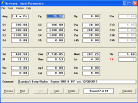
Thanks for responding Art, we old men got to stick together. Attached is what I believe you are asking for, the GBS15 at max voltage. This is the first version of the GBS15 I submitted, so I am sure there are many things wrong with it, but let's worry about that later.
The Parts-Express website states the Dayton PA385s has xmax 10, an in another part of the product description it states that is has xmax 11. I just got a new Parts-Express flyer in the mail yesterday, and that seems to confirm that the xmax is 11.
Attachments
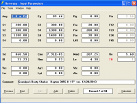
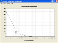

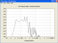
Pretty much what one would expect, your GBS15 is a little bigger and does not go as low, so is a wee bit louder.Thanks for responding Art, we old men got to stick together. Attached is what I believe you are asking for, the GBS15 at max voltage. This is the first version of the GBS15 I submitted, so I am sure there are many things wrong with it, but let's worry about that later.
Try the sim at 75.7volts to see exactly how much louder.
The lesser compression ratio of the GBS15 would have less cone stress and distortion than jwmbro's.
Not as flat as jwmbro's , but in reality probably would be a bit smoother than the sim. Your design could use a Keystone exit to help smooth out the response, jwmbro's is stuck with the build, no tinkering after.
Posts #147/148
Hi DHAA,
You didn't follow the steps I outlined above. 🙂 Had to find a better way. 🙂 Didn't work, did it. 🙂
I don't know why it didn't work, maybe David McBean can explain why the Width/2(cm) column does not maintain an even value after the Export Horn Data Width entry windows have all been set to the same value, und the output Width Flare has been set to Uni. I surely don't know.
If you do it the way I suggested in Post #127 you'll have the same value for all entries in cloumn Height/2(cm) which is the constant width of your box, and an increasing string of values in column Width/2(cm) which is your duct height, and which will result in the correct flare for you design.
Note that you still have to use the advanced centerling method to get you around the 180 degree corner, and that you have to make it fit your 17"x48" side panel, and whatever material you use. I'll attach a sketch of how I do that, I hope it will work for you. It is definitely an iterative process.
On the Mini-Othorn by jwmbro: I think your basic single fold design Posts #47/49 would stack up just fine to it. Yours has more volume, and would probably play a bit louder, it's also not as flat in the passband, which may be a good thing because you might loose some of those peaks when you build, and bandfilter the enclosure. We all don't know what the measured Thiel/Small parameters for this driver will be, so let's not be too eager to squeeze the last little bit out of this design. Also, see Art's analysis in Post #151.
If you want more output you'll have to go w/ a bigger box, e.g.: I did a quick 4 segments Hornresp w/ 4:1 compression ratio, a much bigger mouth, and about V_net=240L, and that really bumps the efficiency and the SPL up.
Regards,
Attachments
Try the sim at 75.7volts to see exactly how much louder.
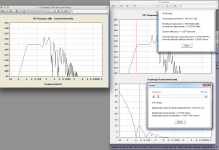
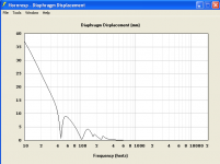
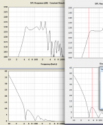
Art, here are the HR screens at 75.7 volts:
Attachments
You didn't follow the steps I outlined above. 🙂 Had to find a better way. 🙂 Didn't work, did it. 🙂
Ah-ha Oliver, I now see what the problem is. I did not follow your directions correctly. The problem lies in the fact that what I consider horn height, you refer to as width, and vice versa. I will try that again tomorrow, doing it correctly, and I am sure that will work.
Thanks for you comments and the attachment you included. I will work on that tomorrow. I am making great progress on mastering SketchUp today, and I don't want to stop now. For anyone interested in learning SketchUp, the book I got today is:
Google SketchUp: The Missing Manual-O'Reilly Media
It was written five years ago for SketchUp 7, but it is still applicable and it is very well written with lots of great examples. I have learned so much today from just reading the first three chapters and playing around a bit.
Hi DHAA,
That height v. width thing got me before, and I just went with what worked. Should have asked David McBean about what is happening, may be a minor bug (if there is such a thing).
Thanks for the link, I'll look into it. Let me know if it holds up as a reference for you.
Regards,
That height v. width thing got me before, and I just went with what worked. Should have asked David McBean about what is happening, may be a minor bug (if there is such a thing).
Thanks for the link, I'll look into it. Let me know if it holds up as a reference for you.
Regards,
Hi DHAA,
Sorry I can't offer any assistance with HR (I need a dumber than dummies guide to get it to work, or far better help section) but I have been using SketchUp for a while now, so if you need a hand give a shout. You should be able to get the exact angle you need using the red, green, blue reference lines and the protractor.
Sorry I can't offer any assistance with HR (I need a dumber than dummies guide to get it to work, or far better help section) but I have been using SketchUp for a while now, so if you need a hand give a shout. You should be able to get the exact angle you need using the red, green, blue reference lines and the protractor.
. . . so if you need a hand give a shout
I was shouting last night for sure, but things have been going a bit better today. Yeah, Silent Screamer I will definitely take you up on your offer to help though. I am done for the day right now, but I will be back tomorrow. Thanks.
Stand back everyone, I stepped into the 3D world tonight and modeled the TSF15 in that there third dimension. Attached is a drawing of the TSF15's in action.
Attachments

Pretty much exactly what I mentioned in #151, yours goes louder with the same input voltage, so when power compression is considered, can do about the same level as the mini-Othhorn with half (or less)the power.Art, here are the HR screens at 75.7 volts:
In the usual club situation, where circuits are limited and voltage drop often prevents amps from putting out full peak power, the more efficient design will outperform even more than the sims show.
Art
Attachments
Pretty much exactly what I mentioned in #151, yours goes louder with the same input voltage, so when power compression is considered, can do about the same level as the mini-Othhorn with half (or less)the power.
Thanks for that comment Art. I really like his design, and James (jwmbro) cab sure looks better, but I guess when it comes to subwoofers, big and ugly might trump small and sexy. That circular cone displacer of his sure looks good though, I may have to incorporate that element at some point. And his 3D drawing looks really professional.
Your design could use a Keystone exit to help smooth out the response.
I sped-read through your Keystone posts when I first started researching tapped horns. Once I get this folding thing under control, I will go back to those posts and try to get a better understanding of that design element.
The biggest flaw I see is using 1/2" rather than 3/4" material for a sub. Saving weight and loosing upper output and "punch" is not a compromise I'd be willing to make. Hornresp assumes inert walls, 1/2" won't be at high power levels.
I am currently redesigned and trying to properly fold the TSF15, using 3/4" plywood per your suggestion. Thanks for your help.
Also, I am not sure if it was you, or someone else's post, but it seems I remember someone built a test model tapped horn that could be partially disassembled to make changes, and then be tested in order to make a fair comparison of design changes. I am starting to think I may try that this spring. Using weather stripping to maintain air-tight seals, I could play around with horn path changes, angled interior corners, cone displacers, etc.. Where I live I don't really have to worry about disturbing the neighbors, and I probably have all the acoustic testing equipment I need already.
Screamersusa did a lot of iterations on his tapped horn, which required more extensive reiterations than the Keystone.I sped-read through your Keystone posts when I first started researching tapped horns.
Also, I am not sure if it was you, or someone else's post, but it seems I remember someone built a test model tapped horn that could be partially disassembled to make changes, and then be tested in order to make a fair comparison of design changes.
The Keystone design came after more than 40 individual tests of different exit sizes and shapes, as well as interior ramps (corner angles) and various other minor changes.
Last edited:
- Status
- Not open for further replies.
- Home
- Loudspeakers
- Subwoofers
- Hornresp Brainiacs - Help an Old Man