Thanks, Just a Guy. I just wanted to make sure I understood that correctly. I've got a busy day going on, but I will try to get that drawing re-posted later today if I can.
One additional question. With such a simple fold as this one, as long as I got the end of the baffle correct,
I forgot to mention that the free end needs to not just drop down a bit, it also needs to move back a bit as well. If you don't move it back there won't be any csa expansion through the first 90 degrees. Other people have fancy spreadsheets and other methods to figure out the bends, for me it's an iterative process. I keep trying until everything agrees with the Horn Data flare length vs csa.
... wouldn't everything else automatically fall into place with the proper dimensions (since the slope of the baffle board stays consistent)? Or are there additional anomalies I should be on the lookout for? Thanks.
If you move the mouth to the end instead of out the side then everything should fall into place. If you don't move the mouth you still have to contend with laying out the last bend properly and getting a correct figure for L23 and L34.
Mouth at end is not as useful as mouth on side for OP's club gig application.If you move the mouth to the end instead of out the side then everything should fall into place. If you don't move the mouth you still have to contend with laying out the last bend properly and getting a correct figure for L23 and L34.
This brings up something I've been meaning to ask for the horn experts here - what equation should be actually used to calculate a parabolic expansion.
I don't have an answer but I do have another question related to the PAR expansion. (This might actually be related to something GM was saying, but I'm not sure since I don't actually know what he meant. Either way, this issue has been bothering me for a long time.)
A PAR segment has a very distinct shape, it can be seen very easily if you create a very large PAR segment.
An externally hosted image should be here but it was not working when we last tested it.
Now let's say we have a simple horn with one PAR segment and during the fold we do a single 180 degree bend. I don't think that accurately reflects the original simulated single PAR segment.
In other words, if you accurately simulated the drawing of the single fold design with a series of PAR segments instead of simulating it as a single PAR segment I don't think the results will be the same. The margin of error will be small due to the relatively small size of any reasonably sized design, but there will be error in both the total volume and the distribution of volume within the flare.
I don't have time to prove this, and don't have the math skills to do it even if I did have the time, but this is one of the many reasons I want the ability to simulate more segments than Hornresp can provide. I'm not happy with the cumulative errors introduced by all the simplifying assumptions we make between simulation and measurement, and a lot of these problems could be avoided. This issue is one of the reasons I'm so excited about the development of TL.app and similar programs that can sim a lot of PAR segments.
Mouth at end is not as useful as mouth on side for OP's club gig application.
I realize that, but this is a just a folding exercise at this point. As such it's probably useful to start with something simple, not a design that the participants of this thread can't even agree on how to approach. Once OP gets a few simple folds under his belt he can attempt to address the driver in a bend issue, or simply avoid it.
It's really too bad you won't discuss it, it would be nice to have confirmation that I'm correct.
It would be nice if Tom critiqued/confirmed mine too, but he hasn't, so until he does...........
GM
(This might actually be related to something GM was saying.....)
A PAR segment has a very distinct shape, it can be seen very easily if you create a very large PAR segment.
Now let's say we have a simple horn with one PAR segment and during the fold we do a single 180 degree bend. I don't think that accurately reflects the original simulated single PAR segment.
It's exactly what I was referring to. When opening the OP's design in the wizard, it doesn't display a parabolic shape, hence the need IMO to design as a conical flare and use the wizard to convert it to one big parabolic flare. Since HR is limited to four segments using straight dividers it seems reasonable to me that any error through the bends will be miniscule at worst IF enough expansion is occurring to keep it from causing a reversion even if not parabolic since the path-length is acoustically tiny.
GM
Par - curved sides v. straight sides
Hi guys,
The Par expansion shown in the Hornresp Schematic Diagram screen is based on circular sections, that's why you see the curved sides. When building a tapped horn we usually have two parallel sides, thus we are using rectangular section, and the horn then displays straight sides on the other two sides.
That's what should be exported from Hornresp, and the way you can do that is (for DHAA):
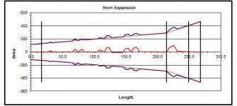
in the Export Horn Data window set all Heights to the constant (parallel sides) horn area dimension you want to build to, e.g.: Post #47 drawing the 17" dimension w/ 23/32" material thickness ends up to be 15.5625"[39.53cm]. So, we'll enter 39.53 (4x). Then we go to the Increment column, and enter a convenient distance, e.g.: 1 cm (3x). Then we must go to the Width Flare column, and pick Uni (there is no Par). Then pick an output File Name, and click Save. Hornresp puts your file into the Hornresp/Export folder, and when we look @ it the first column is the Length(cm) in the increments we entered, and the 8th column is Width/2(cm), this is half the duct height @ the respective length from S1. This is basically what I use to get started w/ the layout. Naturally, if there is a fixed external box dimension and a material thickness given, the trick is to make an appropriate fold, and then to go back into Hornresp, and re-simulate, and so on. If there are no restrictions imposed on the physical outline a closer approximation of the original can be achieved. But, it will most likely always be an iterative process. I'll try to attach a drawing that represents the Hornresp Export Width/2(cm) column done using the script command, and then mirrored around the center line. When you use a CAD drafting program you can pick any point along that flare shape, and list the duct width at that point. You can also measure the flare angle to give you a design starting point. This comes in quite handy when working on a fold.
Regards,
Hi guys,
The Par expansion shown in the Hornresp Schematic Diagram screen is based on circular sections, that's why you see the curved sides. When building a tapped horn we usually have two parallel sides, thus we are using rectangular section, and the horn then displays straight sides on the other two sides.
That's what should be exported from Hornresp, and the way you can do that is (for DHAA):
in the Export Horn Data window set all Heights to the constant (parallel sides) horn area dimension you want to build to, e.g.: Post #47 drawing the 17" dimension w/ 23/32" material thickness ends up to be 15.5625"[39.53cm]. So, we'll enter 39.53 (4x). Then we go to the Increment column, and enter a convenient distance, e.g.: 1 cm (3x). Then we must go to the Width Flare column, and pick Uni (there is no Par). Then pick an output File Name, and click Save. Hornresp puts your file into the Hornresp/Export folder, and when we look @ it the first column is the Length(cm) in the increments we entered, and the 8th column is Width/2(cm), this is half the duct height @ the respective length from S1. This is basically what I use to get started w/ the layout. Naturally, if there is a fixed external box dimension and a material thickness given, the trick is to make an appropriate fold, and then to go back into Hornresp, and re-simulate, and so on. If there are no restrictions imposed on the physical outline a closer approximation of the original can be achieved. But, it will most likely always be an iterative process. I'll try to attach a drawing that represents the Hornresp Export Width/2(cm) column done using the script command, and then mirrored around the center line. When you use a CAD drafting program you can pick any point along that flare shape, and list the duct width at that point. You can also measure the flare angle to give you a design starting point. This comes in quite handy when working on a fold.
Regards,
Attachments
It's exactly what I was referring to. When opening the OP's design in the wizard, it doesn't display a parabolic shape, hence the need IMO to design as a conical flare and use the wizard to convert it to one big parabolic flare.
I don't think that's necessary. HornResp's "par" option was added simply to give a better approximation to what was happening in basically almost all bass horns that are built out of flat panels and folded into a box with two parallel sides. I don't think it was added in order to be able to design a horn that was a parabola from throat to mouth. In my opinion, all that's important is that the model in HornResp be as close a match as possible to the proposed build, and this requires parabolic sections for most bass-horn builds, not an overall parabolic expansion for the build.
For example, I've attached the expansion curve for my recently built POC#2 TH. The expansion is definitely not parabolic overall, but each section is. And the measured results are pretty damned close to what was predicted by HornResp.
Yes, adding more sections to HornResp may result in an even more accurate sim, but the question really is - does the difference make a difference? Frankly, I'd be more concerned about ensuring the built system is properly sealed and braced so it doesn't boom like a drum and walk all over the floor like a off-balance washing machine when the power is turned up, than a sim that shows an extra 0.5 dB here and there.
Attachments
Hi guys,
The Par expansion shown in the Hornresp Schematic Diagram screen is based on circular sections, that's why you see the curved sides.
I guess I should have paid more attention in math class. So you are saying that a single PAR segment when folded in half is still mathematically correct at all points of csa vs length? If so, my post #123 is invalid in it's entirety and can be ignored. In fact, if you can confirm this I'll request that it be deleted to avoid any confusion.
Anyway, in response to GM's post:
... hence the need IMO to design as a conical flare and use the wizard to convert it to one big parabolic flare.
I don't think it needs to look parabolic as a whole in the first place, but even if this is desired, simulating conical segments and using the wizard to change the shape of the schematic by eye using PAR segments so it looks like one big PAR flare does not seem accurate to me. I'm not mathematically skilled enough to determine the margin of error this would produce, but I can think of at least 3 alternative methods to avoid having to do this altogether, listed here in order of accuracy from most accurate to least.
1. Use a simulator that can simulate a large number of PAR segments and simulate the flare exactly as it would be built. This would seem to have no margin of error at all.
2. Use the flare frequency and segment length of the original segment and transpose that flare frequency and segment length to the new segment(s). I don't know how to find the flare frequency of PAR or CON segments, but since Hornresp reports it for all exponential and hyp/ex flares I assume there's a way to find out what it is for PAR and CON segments as well.
3. Use the volume and shape of the original flare segment and approximate it using the same flare shape and volume with the new segment(s).
Last edited:
Just to be really really clear about this (because as I mentioned it's been bothering me for a long time now) both of you (tb46 and Brian Steele) are saying that this simple circular single segment simulation (PAR segment):

is mathematically exactly the same as this 3d rectangular folded single segment schematic:

and both pictures will have exactly the same csa vs length at every point along the line length (assuming the same throat and mouth area in both and assuming path length through the bend is accounted for properly)?
is mathematically exactly the same as this 3d rectangular folded single segment schematic:
and both pictures will have exactly the same csa vs length at every point along the line length (assuming the same throat and mouth area in both and assuming path length through the bend is accounted for properly)?
Last edited:
Hi just a guy,
Somewhere in the "Collaborative Thread" there is a discussion of the Par - and other - expansion. And I haven't been able to find it yet, but I found a reference in the Hornresp thread, see this page: http://www.diyaudio.com/forums/subwoofers/119854-hornresp-18.html
As to your question, Post #129: "...So you are saying that a single PAR segment when folded in half is still mathematically correct at all points of csa vs length?..." Yes, that's what I have been trying to say, that's why you are correct to point out that the error in the 180 degree bend messes it all up. So you try to approximate the expansion through a bend using the Soho54 "advanced centerline method" to give you the segment length for the bend otherwise you'll maintain the same angle as long as the flare rate has not been altered (which by definition it has not been using Hornresp,and a single segment from front to back of driver (L23)).
To get a different overall flare rate (as jbell did w/ the SS15) you just simulate the individual sections to add up to that desired overall flare rate; but when building: each individual horn section will still have a Par expansion if it is build w/ straight sides between two parallel sides.
Regards,
Hi just a guy,
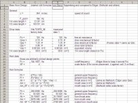
My eyes are getting tired, but I found a spreadsheet I use on occasion to generate basic design points for horn systems. I has a few names in it as to where I got some of the formulas, but they all basically go back to the ancients even before the now late Mr. Leach, who pulled it all together in his horn paper. This is a bit rough and tumble, and needs more work, and a few more formulas, but maybe you can get something out of it. Hey, maybe GM will critique it.
Regards,
Attachments
Last edited:
I don't think that's necessary. HornResp's "par" option was added simply to give a better approximation to what was happening in basically almost all bass horns that are built out of flat panels and folded into a box with two parallel sides. I don't think it was added in order to be able to design a horn that was a parabola from throat to mouth. In my opinion, all that's important is that the model in HornResp be as close a match as possible to the proposed build, and this requires parabolic sections for most bass-horn builds, not an overall parabolic expansion for the build.
Yes, adding more sections to HornResp may result in an even more accurate sim, but the question really is - does the difference make a difference? Frankly, I'd be more concerned about ensuring the built system is properly sealed and braced so it doesn't boom like a drum and walk all over the floor like a off-balance washing machine when the power is turned up, than a sim that shows an extra 0.5 dB here and there.
You’re ‘preaching to the choir’: http://www.diyaudio.com/forums/subwoofers/248026-hornresp-brainiacs-help-old-man.html#post3754730
Please make up your mind though, you say my way isn’t necessary, then explain why it is.
BTW, the actual expansion for these parallel wall ‘parabolic’ [T]Hs are all ~hyperbolic as all hover around a 0.5 M[T] due to having no compression chamber per se.
Not to me since they’re only needed for designing very long, wide BW horns where many folds are usually necessary and ideal radius curves isn’t an option.
Yes, maintaining acoustic efficiency is key to a successful bass horn alignment, especially at higher power.
GM
Ahhhh, you mofo C*#&*# s*@* a*$(@$(*#@$ SketchUp. Ahhhhhhh!
O.K., I got that out of my system.
First off, interesting discussion going on tonight. I am not totally comprehending what exactly is going on, but it is good to see you guys having differences of opinions. It's not just me trying to reverse engineer your designs, It's you also trying to reverse engineer the Danley models, and take it even further. It looks like everyone has their thinking cap on tonight.
Ahhhh, you mofo C*#&*# s*@* a*$(@$(*#@$ SketchUp. Ahhhhhhh!
O.K., I got that out of my system again.
Thanks again, Oliver. After a quick dinner tonight I cranked up Hornresp and SketchUp and went to work. I actually seemed to figure out the Hornresp horn export myself, and how to apply it, but I made some critical mistakes in my export and it has been all downhill since. Here is what I seemed to do wrong in the Hornresp horn export:
Increment: When I opened the Hornresp horn export I thought about what needed to be done, and changed the widths to match the internal width of my design. I saw that the heights then changed to the proper dimensions, so all was good so far. Then the Increment setting came preset to S2: 0.500, S3: 2.00, S3: 0.500. I thought about it for a while and couldn't see any good reason for S3 being different than S1 and S2, so I changed S3 to 0.500 to match the others. I will try tomorrow setting all of them to 1.00 like you just recommend.
Width Flare: I saw there was no way to select PAR. I seemed to remember a previous point someone made that to export to Akabak you need to use CON. So that is what I did. Well, when I tried to plot that out in my SketchUp drawing it was one problem after another. Somethin' ain't right. I wish I would have checked in to see what was going on with the forum and seen this excellent post of your earlier, but I was trying to figure this out for myself and was in a zone. I will start over tomorrow, use UNI, and follow your direction to the letter, and hopefully that will clear this mess up.
Ahhhh, you mofo C*#&*# s*@* a*$(@$(*#@$ SketchUp. Ahhhhhhh!
Goodnight Gentlemen, I got the feeling I will be having SketchUp nightmares tonight. Aaaaahhhhhhhhh!
O.K., I got that out of my system.
First off, interesting discussion going on tonight. I am not totally comprehending what exactly is going on, but it is good to see you guys having differences of opinions. It's not just me trying to reverse engineer your designs, It's you also trying to reverse engineer the Danley models, and take it even further. It looks like everyone has their thinking cap on tonight.
That's what should be exported from Hornresp, and the way you can do that is (for DHAA):
in the Export Horn Data window set all Heights to the constant (parallel sides) horn area dimension you want to build to, e.g.: Post #47 drawing the 17" dimension w/ 23/32" material thickness ends up to be 15.5625"[39.53cm]. So, we'll enter 39.53 (4x). Then we go to the Increment column, and enter a convenient distance, e.g.: 1 cm (3x). Then we must go to the Width Flare column, and pick Uni (there is no Par). Then pick an output File Name, and click Save. Hornresp puts your file into the Hornresp/Export folder, and when we look @ it the first column is the Length(cm) in the increments we entered, and the 8th column is Width/2(cm), this is half the duct height @ the respective length from S1. This is basically what I use to get started w/ the layout. Naturally, if there is a fixed external box dimension and a material thickness given, the trick is to make an appropriate fold, and then to go back into Hornresp, and re-simulate, and so on. If there are no restrictions imposed on the physical outline a closer approximation of the original can be achieved. But, it will most likely always be an iterative process. I'll try to attach a drawing that represents the Hornresp Export Width/2(cm) column done using the script command, and then mirrored around the center line. When you use a CAD drafting program you can pick any point along that flare shape, and list the duct width at that point. You can also measure the flare angle to give you a design starting point. This comes in quite handy when working on a fold.
Ahhhh, you mofo C*#&*# s*@* a*$(@$(*#@$ SketchUp. Ahhhhhhh!
O.K., I got that out of my system again.
Thanks again, Oliver. After a quick dinner tonight I cranked up Hornresp and SketchUp and went to work. I actually seemed to figure out the Hornresp horn export myself, and how to apply it, but I made some critical mistakes in my export and it has been all downhill since. Here is what I seemed to do wrong in the Hornresp horn export:
Increment: When I opened the Hornresp horn export I thought about what needed to be done, and changed the widths to match the internal width of my design. I saw that the heights then changed to the proper dimensions, so all was good so far. Then the Increment setting came preset to S2: 0.500, S3: 2.00, S3: 0.500. I thought about it for a while and couldn't see any good reason for S3 being different than S1 and S2, so I changed S3 to 0.500 to match the others. I will try tomorrow setting all of them to 1.00 like you just recommend.
Width Flare: I saw there was no way to select PAR. I seemed to remember a previous point someone made that to export to Akabak you need to use CON. So that is what I did. Well, when I tried to plot that out in my SketchUp drawing it was one problem after another. Somethin' ain't right. I wish I would have checked in to see what was going on with the forum and seen this excellent post of your earlier, but I was trying to figure this out for myself and was in a zone. I will start over tomorrow, use UNI, and follow your direction to the letter, and hopefully that will clear this mess up.
Ahhhh, you mofo C*#&*# s*@* a*$(@$(*#@$ SketchUp. Ahhhhhhh!
Goodnight Gentlemen, I got the feeling I will be having SketchUp nightmares tonight. Aaaaahhhhhhhhh!
Last edited:
Hi just a guy,
My eyes are getting tired, but I found a spreadsheet I use on occasion to generate basic design points for horn systems. I has a few names in it as to where I got some of the formulas, but they all basically go back to the ancients even before the now late Mr. Leach, who pulled it all together in his horn paper. This is a bit rough and tumble, and needs more work, and a few more formulas, but maybe you can get something out of it. Hey, maybe GM will critique it.
Regards,
I can make a couple of comments but I don't have time right now to look up all the formulas and comment on all of it.
First, as GM pointed out in this thread, and as I found out about 4 or 5 years ago when I figured out I could beat the Labhorn in xmax limited spl and with smoother response (on paper at least) in the same net volume and with the same tuning just by playing with the sliders, sometimes all the formal math isn't all it's cracked up to be. For me, figuring out Leach's math and GM's post processing design routine have been a type of holy grail, but mostly on an intellectual level, not because I want to do exactly what Leach and GM do.
Second, if you want to seriously pursue this, I would narrow it down to one person's math. Most people seem to narrow it down to Leach and his famous horn paper. There are a lot of big names and they all do things a bit different, and that will be confusing unless you follow one method, at least to get the hang of it.
The first problem I see on your sheet is that Fc is not arbitrary. You can choose it arbitrarily if you want I suppose, but it's clearly defined in Leach's paper as wc/(2pi) under 6.1 System Specifications. But then you need to find wc, which is the square root of wl*wh. To find out wl and wh you need Qtc, which is wc/wl+wh. And we still don't know what wl and wh are, so you can see this can be maddening if you don't put ALL the formulas into a spreadsheet. I don't even remember exactly how I figured out what wl and wh actually are, but IIRC I never would have figured it out without the help of someone else's spreadsheet so I could follow the formulas all the way back.
Having said all that, I don't even attempt to use the math now that I've figured it out, I mostly use Hornresp's System Design tool (With Driver or From Specifications depending on what I'm trying to do) and that's by far the easiest implementation of Leach's math that I've ever found yet. If I need to know the value for one of the intermediary steps or if I need to find the highest efficiency possible I use a Leach math spreadsheet.
If you do choose to use Hornresp's System Design feature, you will find that it (almost?) always tries to give you a .8T flare, which (almost?) always gives you a throat that is way too small and a rear chamber size that might not even be big enough to physically accommodate the driver. To avoid these issues there's two things you can do, either change the desired bandwidth or (since a Hornresp update last summer) you can now manually change the flare T, ideally to the value given by Leach's math. That will bring everything into reasonable proportions and will give a full sized fully reactance annulled design for any driver and bandwidth combination I've tried so far. From there you can check and make sure the efficiency is where it needs to be.
That leaves one problem. The math (and by extension, all Leach math spreadsheets and the Hornresp System Design tool) will give you a full sized ideal horn which will be about the size of a garden shed for a 30 hz tuning. The Labhorn is the only subwoofer I know of that was designed using Leach's math and it was designed as a stack of 8, not a single cab, and even then the plans reflect a 1/8 size design that was even further shrunken considerably from the original Leach math design. And there's nothing you can do about the size issue unless you can figure out GM's design routine. So even if you use all the published math to your best advantage you still won't get something that's a reasonable size for domestic situations.
I guess this is a long way of saying be careful what you wish for, if you are math impaired like I am, and wish to take this any further than basic design points, this pursuit could suck up a large portion of your life, and even if you are good at math I can't imagine it will be easy.
Moving on, Fl and Fh describe the gain bandwidth, not "general upper and lower frequency" as you have marked. (This is a small distinction but important if you want to really understand what's going on.) And as GM pointed out in a different thread just a few days ago, it might be better to use Qes in those formulas instead of Qts. As far as the rest of the formulas on your sheet, I don't have time right now.
If you want to discuss Leach's math in more detail, just email me. From all my years on the forums, you, me, GM and Danley are the only ones that I have ever seen express any interest whatsoever in using math to design horns, so I imagine this conversation is not very useful to this thread and will probably be considered very boring. This is a good thread, I don't want people to get bored and lose interest.
Last edited:
Please make up your mind though, you say my way isn’t necessary, then explain why it is.
Your way is necessary if you use your design routine (although I still think there are much better ways to do it than adjusting the wizard by eye so the flare looks parabolic in the schematic). No one else is using your design routine so it isn't necessary for anyone else.
Anyway, there's a good bit of difference in the appearance of a .5 T flare and a PAR expansion even if they are the same length (the hyp/ex flares more prominently at the end of the line whereas the PAR flares more prominently at the beginning) so there is at least some margin of error going on here no matter how you convert the flare type unless you curve the boards and actually build the correct hyp/ex flare T that you originally simulated.
Last edited:
Acoustic intensity = p ^ 2 / (rho * c )
I forgot to add that the above formula is simply a more "user friendly" alternative to the 'p * v' expression given by James. It enables SPL to be readily calculated when the sound output power is known.
Kind regards,
David
The only possible improvement I can think of is if somehow there could be a way to save all the driver parameters, so you could easily swap out different drivers in a cabinet design, for a quick comparison.
Thank you Sir for all the work you have put into Hornresp. I believe I may be addicted though!
Hi DHAA,
Thanks for your kind words 🙂.
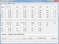
Menu commands File > Copy Driver (or shortcut Ctrl+C) and File > Paste Driver (or shortcut Ctrl+V) can be used to quickly insert a different set of driver parameter values into a given design - the design record needs to be in edit mode to accept the new values.
Some users have even gone to the trouble of setting up records containing driver parameters only, which they then call upon for their designs as necessary. For example, a comment field might read "# Eighteen Sound 10W400 driver". The '#' identifies a driver record, and comes in useful when searching with the Find and Sort tools. See attached example.
Kind regards,
David
Attachments
Your way is necessary if you use your design routine (although I still think there are much better ways to do it than adjusting the wizard by eye so the flare looks parabolic in the schematic). No one else is using your design routine so it isn't necessary for anyone else.
Anyway, there's a good bit of difference in the appearance of a .5 T flare and a PAR expansion even if they are the same length (the hyp/ex flares more prominently at the end of the line whereas the PAR flares more prominently at the beginning) so there is at least some margin of error going on here no matter how you convert the flare type unless you curve the boards and actually build the correct hyp/ex flare T that you originally simulated.
Excuse me?! It has absolutely nothing to do with my design routine per se! If you’re not using a ~hyperbolic flare, then you’re ‘missing the boat’ WRT bass TH design AFAIK, which BTW is so close to conical in the path-lengths generally used that this is what we’re actually trying to ‘close enough’ convert, but I’ll leave that for Dave to clarify just how close it actually is.
GM
The equation I use in my spreadsheet to estimate the expansion between S1 to S4 is as follows:
S(d)=((S2-S1)*d/L)+S1
Where
S1 = cross-section at the start of the path
S(d) = cross-section at point "d" on path
S2 = cross-section at the end of the path
L = path length
Hi Brian,
Assuming that you mean "S1 to S2" rather than "S1 to S4", then your formula for calculating the cross-sectional area at any point along a parabolic horn is correct. The parabolic horn is probably the simplest to compute because cross-sectional area increases linearly with distance.
Kind regards,
David
- Status
- Not open for further replies.
- Home
- Loudspeakers
- Subwoofers
- Hornresp Brainiacs - Help an Old Man