Since the late 90's to now there has been a steady progression of 5 string basses, so the usual low note in rock & roll has dropped from 41 to 32 Hz.Thanks for the info Art. The interchangeable "plates" look interesting - thanks for sharing that graphic. That idea may prove very useful for my needs, as I will be building these for three different generations of people. It seems each generation want's to go lower.
Synths can play way lower than that, and cost less than a decent guitar.
It is common to hear plenty of content down to 30 Hz (and lower) in pop music now, back in the vinyl days few records had lower than 50 Hz.
The change in music is what made me change out the LF in my system four times in the last two decades.
The compromise at around a 35 Hz F3 will probably be as low as I go for portable use, cabinet size or power demands just get too much when you try to reach lower, and few people can tell the difference- most think that "feeling it in the chest" is low, and that actually happens more in the 60-100 Hz range.
Feeling your trousers flapping happens down in the <40 range, but the tight jeans in fashion don't allow that as well, though worn at half mast there are probably plenty of "jingle bells" now 😉.
Art
Post #260
Hi DHAA,
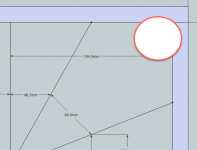
Is that still the flare that I had in Post #127 w/ a 7.238 degree angle, what is the drawn material thickness (the 19.0mm is @ an angle to the board), what are the outside dimensions of the finished box?
Going around the bend you go from 173.2-90°-194.9-19.2-196.7-90°-201.5. That's close, but doesn't look quite correct yet. 1st bend difference 194.9-173.2=21.7 - 2nd bend difference 201.5-196.7=4.8; the difference should be greater in the second bend, so something is amiss.
In the real world this doesn't matter, but you're trying to get it perfect in SketchUp.
"Once more into the breach."
Regards,
Hi DHAA,
Is that still the flare that I had in Post #127 w/ a 7.238 degree angle, what is the drawn material thickness (the 19.0mm is @ an angle to the board), what are the outside dimensions of the finished box?
Going around the bend you go from 173.2-90°-194.9-19.2-196.7-90°-201.5. That's close, but doesn't look quite correct yet. 1st bend difference 194.9-173.2=21.7 - 2nd bend difference 201.5-196.7=4.8; the difference should be greater in the second bend, so something is amiss.
In the real world this doesn't matter, but you're trying to get it perfect in SketchUp.
"Once more into the breach."
Regards,
Oliver,Going around the bend you go from 173.2-90°-194.9-19.2-196.7-90°-201.5. That's close, but doesn't look quite correct yet. 1st bend difference 194.9-173.2=21.7 - 2nd bend difference 201.5-196.7=4.8; the difference should be greater in the second bend, so something is amiss.
In the real world this doesn't matter, but you're trying to get it perfect in SketchUp.
Once Gramps puts in a grab handle, the expansion will be perfect 😀.
Art
Attachments
Is that still the flare that I had in Post #127 w/ a 7.238 degree angle, what is the drawn material thickness (the 19.0mm is @ an angle to the board), what are the outside dimensions of the finished box?
Going around the bend you go from 173.2-90°-194.9-19.2-196.7-90°-201.5. That's close, but doesn't look quite correct yet. 1st bend difference 194.9-173.2=21.7 - 2nd bend difference 201.5-196.7=4.8; the difference should be greater in the second bend, so something is amiss.
In the real world this doesn't matter, but you're trying to get it perfect in SketchUp.
"Once more into the breach."
Oliver, you are too good at this, my friend. I have done quite a few revisions and HR Horn Exports, so I am not honestly sure what is what anymore. Also, you didn't hear this from me, but the word finagle comes to mind.
Finagle: To obtain or achieve by indirect, usually deceitful methods
I have a busy weekend but I will start over again on Monday. Don't give up hope yet though, I think I ALMOST understand what I should be doing. Thanks.
Feeling your trousers flapping happens down in the <40 range, but the tight jeans in fashion don't allow that as well, though worn at half mast there are probably plenty of "jingle bells" now 😉.
I knew I had been saving those bell bottom jeans from my youth for a good reason. I will dust them off and they will become an integral part of my subwoofer testing gear.
Once Gramps puts in a grab handle, the expansion will be perfect 😀.
Nice save ART!!! Thanks. Keep the faith.
Hi DHAA,
It's good to take a little break every now and then. I'll try to find the time to explain the way I actually do it again, maybe I'll communicate it a little better.
Have a great weekend.
Regards,
It's good to take a little break every now and then. I'll try to find the time to explain the way I actually do it again, maybe I'll communicate it a little better.
Have a great weekend.
Regards,
Hi DHAA,
Is that still the flare that I had in Post #127 w/ a 7.238 degree angle, what is the drawn material thickness (the 19.0mm is @ an angle to the board), what are the outside dimensions of the finished box?
Going around the bend you go from 173.2-90°-194.9-19.2-196.7-90°-201.5. That's close, but doesn't look quite correct yet. 1st bend difference 194.9-173.2=21.7 - 2nd bend difference 201.5-196.7=4.8; the difference should be greater in the second bend, so something is amiss.
In the real world this doesn't matter, but you're trying to get it perfect in SketchUp.
"Once more into the breach."
Regards,
Hey, I'm back again. I didn't die, and I am not giving up on this. I even got some new eye glasses, so here we go:
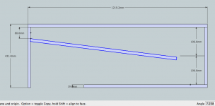
Oliver, I am starting over again. Here is what I have:
- An cabinet with exterior dimensions of 1219.2mm x 431.8mm, built with 19mm thick plywood.
- The baffle board is currently 1000mm (it will have to be trimmed) also built with 19mm plywood.
- I mount the bottom end of the baffle board to the bottom of the cabinet, offsetting it 80mm from the rear of the cabinet.
- Then I angle the baffle board 7.238 degrees (as you had suggested in post #127).
- But either something is wrong here, or I am completely misunderstanding the proper folding of a tapped horn.
- The interior depth of the cabinet is 393.6mm, so you can see from the attached drawing that I put a center line in, spaced 196.8mm from the front and back of the cabinet.
- Look at the baffle board in relationship to the centerline I drew. I believe the baffle board should be closer to the rear of the cabinet at it's end point, because the horn path is constantly expanding and it need a bigger area as it goes over the bend. But instead, the baffle board is closer to the front of the cabinet.
So, what is wrong here? Thanks.
Attachments
Last edited:
Hi DHAA,
Post #127 - shows a horn flare
Post #152 - shows a first step at laying out the enclosure (but, as it says, it is not there yet).
Post #268 - You are defining the exterior dimensions as: 1219.2mm x 431.8mm x 431.6mm (interior depth 393.6mm + 2x19mm walls), and you are saying you are using a 7.238° baffle board angle. You have placed the horn mouth to the side.
I don't think Post #268 is derived from the flare shown in Posts #127/152 so there is no 7.238° angle requirement.
It's an iterrative process:
1. You design in Hornresp, export a flare, adopt a basic layout (e.g.: single fold as you are trying now), and let the wood fall where it may.
2. You start out as in 1. above, but adjust the flare to fit an arbitrary set of dimensions in wood. Then you take the new length and area dimensions back into Hornresp to see what you got.
I think you are trying 1. and 2. at the same time, that will most likely not work.
I'll try to find some time later, or tonight, to look at this some more. Maybe Brian Steele can help you w/ his computerized folding method.
Regards,
. . . I don't think Post #268 is derived from the flare shown in Posts #127/152 so there is no 7.238° angle requirement.
It's an iterrative process:
1. You design in Hornresp, export a flare, adopt a basic layout (e.g.: single fold as you are trying now), and let the wood fall where it may.
2. You start out as in 1. above, but adjust the flare to fit an arbitrary set of dimensions in wood. Then you take the new length and area dimensions back into Hornresp to see what you got.
I think you are trying 1. and 2. at the same time, that will most likely not work.
Thanks for clearing that up for me Oliver.
I actually think I understand what I should be doing. Part of my problem is that I am using three different computers to work on this and I have so many different revisions and horn data exports going that I think I may be mixing up some of the details.
Also, continually converting from inches to mm/cm (and back again) may be another source of my troubles.
I was actually playing around with Brian Steel's spreadsheet over the weekend. I will put a bit more effort into understanding how that works.
I think I am going to pick a new driver, design new taped horn, and just start over. I will do all measurement in mm. to remove that elements as a source of confusion. I will build a full sized layout on a piece of paper to have that to use as a visual aid and to check my work.
I have a project here at work I need to devote a lot of time to for the next week or so, but I will check back in here when I have something respectable to present. Thanks again for all the help everyone here has given me.
Hi DHAA,
I agree the back and forth w/ metric and imperial dimensions gets to be confusing.
I just looked at your last post again, and you are doing 17"x17"x48" as in the original attempt. The final for that is in Post #62. Note the different S1 duct height, and the different baffle angle.
It's probably best if you start from scratch. That way we'll have a specific Hornresp Input to refer to, etc.. And we'll use whatever dimension scheme you want to use.
Regards,
So, what is wrong here? Thanks.
I haven't followed all the folding posts as I have my own way [well, the way the pioneers 'taught' me], but you have to factor in the bend's aspect ratio, so in a side view the divider board's offset could be centered and really only know if it's flat out wrong is if it moves past the center-line to the terminus side of the fold.
GM
I had experimented with folding using graph paper, but I think I was making my models too small. Do you model the horn on a larger scale, cut it up and re-arrange it, then re-draw it again? If this is the approach you use, what scale do you do it in? Thanks.
I think I mentioned 3 or 4 times that I draw out the fold with paper and pen. You have to be able to measure very accurately to get your segment lengths if you do it that way, or you can just draw it in Sketchup, but either way you will probably end up having to draw it (or at least edit it) several times before you get it right.
I thought about this a lot, trying to find a way to explain how to fold without typing for several hours. I couldn't think of a way so I didn't respond. I'll give it a quick shot here and cover a couple of points but keep in mind there are several ways to approach any given fold and dozens of tricks to make things easier.
So let's start with what we know. We know we have a sim we want to fold, we know we want a single fold and we know that any PAR segment (or collection of PAR segments) that is folded back onto itself will create a perfect rectangle. Without even looking at the Horn Data export chart, we know the throat area, the mouth area, (as well as the area of S2 and S3) the length of each segment and the net volume of the horn.
An externally hosted image should be here but it was not working when we last tested it.
How do we figure out how long the box should be? There are at least a couple of different ways to figure this out. First, we could take the net volume as reported by Hornresp, add a few liters (maybe 10 or so) to account for extra space in the bend corners, add in the volume of the divider panel, take that number and divide it by the dimensions of the known end of the box, and get the interior box length that way. Or we can just start drawing it out segment by segment and put the bends where we think they should go. And there are a couple of more advanced ways to find the box length that would require too much explanation.
The last thing we need to know is where the free end of the panel divider should be. We already know the angle it's headed, we just need to know where it ends. We can estimate the percentage of horn length at it's end (the point closest to the far box wall) and check the Horn Data export to find the csa at that point. Divide that number by the box width (or height, depending on your perspective) and that will tell you how much space is between the far end of the box and the free end of the panel divider.
At that point you draw in the box and draw in the advanced centerline, you measure the advanced centerline and if the total centerline length does not match the line length in the simulation, you redraw the box with a different box length and try again. It could take a couple (or several or hundreds) of iterations to get it right. It's a lot of work and it takes a lot of time but all the steps are very simple.
Once you get it to the point that the advanced centerline length looks right, you can use the Horn Data export chart to make sure that the csa vs length is correct at all points in the horn, and if it is you are done.
I didn't have a lot of time to spend on this, so it's very short and undetailed but hopefully it's clear enough. Just remember, there are several ways to approach any given fold and dozens of tricks to speed things up. This will all become very clear when you get some experience with how all this works. Look at it like an algebra problem, find out what you know and what you need to know (what you need to know is usually less than you think) and find the fastest and easiest way to solve for the unknowns.
Last edited:
No built cabinet will ever measure exactly like a simulation, period, full stop.
Art
I think a full stop right at that point is a bit misleading. What I quoted is true, but let me add a qualifier.
This is a Hornresp sim vs an Akabak sim vs a real measurement of a Lilmike F20 cab (a fairly complex horn) from the folding link I provided earlier. The sims are pretty close to the measurement. Not perfectly accurate but pretty close for a 1d sim that ignores a lot of real world factors. I continually strive for more accuracy, even if that just means knowing the reasons why the sim and the measurement don't match exactly.

Just a Guy,...At that point you draw in the box and draw in the advanced centerline, you measure the advanced centerline and if the total centerline length does not match the line length in the simulation, you redraw the box with a different box length and try again. It could take a couple (or several or hundreds) of iterations to get it right. It's a lot of work and it takes a lot of time but all the steps are very simple.
Once you get it to the point that the advanced centerline length looks right, you can use the Horn Data export chart to make sure that the csa vs length is correct at all points in the horn, and if it is you are done.
You covered the details well.
In DHAA's case, it appears he has decided on a 48" height to maximize plywood, though capping the ends he could go to 49.5".
That difference would hardly be measurable, but using cap ended top and bottom makes a better cabinet for the road and for stacking on top of.
Using a just one additional bend at the bottom with a slightly deeper cabinet an additional 17" or so of path length could be added to the OP's design, which would make a measurable, lower response.
I always try to design for truck box integers (90, 45, 30, 22.5, 15, 11.25") so am in the same boat, the dimensions are fixed, allowing only so much variety of folds, so the iterative process is determined by path length, then the path length put in Hornresp to determine what the outcome may be.
Just a Guy,
You covered the details well.
In DHAA's case, it appears he has decided on a 48" height to maximize plywood, ...
If you determine the dimensions first everything becomes easier, you just change the sim to match your plans. (IIRC this is how Ricci designed the Othorn and Gjallerhorn, he started with external box dimensions and then iterated different panel positions within this framework to find the best compromise.)
The problem is that if you are trying to accurately fold a sim and you don't want to change the sim, the length dimension of the box is the only one that you can't pick before you start. Depending on the aspect ratio of the box, different internal widths will call for different box lengths to maintain the simulation's line length.
(I'm sure you know all that, I'm just saying it for the OP.)
I always try to design for truck box integers (90, 45, 30, 22.5, 15, 11.25") ...
How important is this in the real world? I did a quick check once and IIRC I found that there is no real standard truck size, so why is everyone shooting for standard pack dimensions?
They are pretty close, with the exception that the measured response is -5 dB at 20 Hz from the simulations, rolling off almost 1/3 octave higher, at a lesser rate.This is a Hornresp sim vs an Akabak sim vs a real measurement of a Lilmike F20 cab (a fairly complex horn) from the folding link I provided earlier. The sims are pretty close to the measurement.
Since the cabinet is designed for 20 Hz response, that is a pretty large shortfall, -5 dB at 20 Hz sounds half as loud, and would require nearly four times the power to correct, assuming excursion was available.
Could be the measurement mic is deficient down at 20 Hz, but the less steep measured rolloff makes me think that is not the case.
My one attempt at an FLH using Hornresp fell similarly short in the LF response as Lilmike's (also about 1/3 octave higher rolloff than predicted, and I know my measurement mic was not the problem), though the THs I have built have been closer to the simulation, other than they don't go lower in multiples like predicted.
Anyway, no complaints here, just observations.
Art
Very important.How important is this in the real world? I did a quick check once and IIRC I found that there is no real standard truck size, so why is everyone shooting for standard pack dimensions?
Modern USA semi trailers are like 104" interior, but that is a different game than the usual rental truck market, their boxes usually allow for an inch or two wiggle room if you figure for a 90 inch box.
Rental trucks may be wider now that the 8' exterior width is no longer in force, but there are literally millions of older box trucks still in use and in the rental market.
I once had an employee go out to purchase a 24' used straight truck that seemed to fit our needs.
He measured the box width at the bottom at around 91.5", adequate so we could put E-track in and still fit our 90" loads.
Turned out that the upper box width was less than the bottom, requiring a lot of shoving to get the upper cabinets in at the front of the truck, and difficulty pulling the wedged in cabs out.
After a few weeks in service, the truck became known as the "Squeeze Box" 🙄.
Art
This is a Hornresp sim vs an Akabak sim
Hi just a guy,
You are comparing a power response (Hornresp) to a pressure response (AkAbak). If the Hornresp response is compared against an AkAbak power response, for a script exported from Hornresp, you should find that the results are identical.
Kind regards,
David
- Status
- Not open for further replies.
- Home
- Loudspeakers
- Subwoofers
- Hornresp Brainiacs - Help an Old Man