Hi,
if a horn loaded driver is 50% efficient, then half the input power is converted to heat in the voice coil and the other half is converted to acoustic energy.
Let's suppose we have used an 8ohm driver with an Re=6r0 in this near perfect horn.
What is the effective load impedance seen by the amplifier when operating in the passband of the horn loaded driver?
Could it be 8ohm or 12ohm or 16ohm?
or some other value?
Interesting question.
I always thought the horn was a "transformer" matching the acoustic impedance of free-space to the acoustic source impedance of the motor. So rather than the resonant peak(s) of a box enclosure I'd expect a step up in impedance at the low frequency limit of the horn to a parallel combination of transformed free space impedance and the motor impedance. Never measured one though.
Can't wait to see a graph. anyone?
The measured impedance will certainly rise. Programs like hornresponse can model this.
Regards
Charles
Regards
Charles
Thanks GM,
why does horn resp not show this? It does not seem to show on the impedance graph.
Since most of our modern amplifiers are constant voltage, then a 100W into 8ohm amplifier will deliver that same 40Vpk into 12ohm rather than the 8ohms normally assumed.
Does that mean we have 33W of heat and 33W of acoustic power?
A bit better than 98W of heat and 2W of acoustic power.
Is this why Tom Danley says you can use a 2kW amplifier to drive the Labhorn?
You're welcome!
Dunno, my experience with Hornresp is very limited since I find it such an infuriating/frustrating experience to use and I feel my quality time is better 'spent' on more productive 'projects'. My mind just doesn't 'process'? like a programmer's?/how it must be programmed?/whatever. That said, most folks don't know how to design a 'perfect' horn (including some 'pro' horn designers if they're not intentionally playing 'dumb'), so even if Hornresp will accurately predict one, it's only as 'smart' as the person doing the inputting. Hopefully you'll pardon me for not going into detailed theory, but FWIW, attached is the closest I could come using MJK's original horn Mathcad WS. I haven't taken the time yet to research his latest one, so don't know if I can improve on it or not.
Since I had no use for the LABhorn I didn't follow its thread, etc., to any great extent, but being a TD design I assume it's a Leach math optimized alignment and it's my understanding that its dual drivers are basically 'bullet-proofed' single coil Avatar/Adire Shivas, so yeah, it should be able to handle plenty of power if wired in parallel and driven with a typical vanishingly low output impedance SS amp.
GM
Attachments
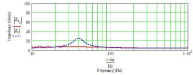
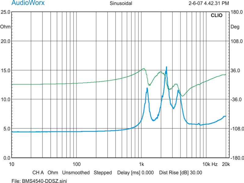
It's more complicated than a simple rise. Most horns, even relatively benign "waveguides," introduce a number of lumps/peaks in the impedance curve. Borrowing some pics from JonMarsh at HTGuide.....
DDS ENG1 waveguide and BMS4540 driver:
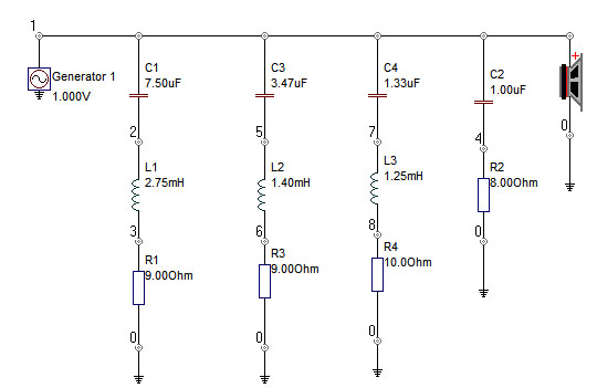
Conjugate network to flatten impedance (no crossover yet):
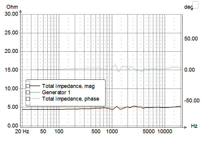
Impedance with network:
DDS ENG1 waveguide and BMS4540 driver:
Conjugate network to flatten impedance (no crossover yet):
Impedance with network:
As already stated the minimum impedance is going to double to 12ohms. Since you are talking about a 50% efficient system, by definition half the power is going into the voice coil as heat, the other half goes into the air as acoustic power. This means there can't be any other losses in the system. Some of the resonances in the system will therefore have infinite Qs, since there is no damping on them. The impedance curve will have peaks into the hundreds of ohms range.
AndrewT said:Thanks GM,
why does horn resp not show this? It does not seem to show on the impedance graph.
Hi AndrewT,
As far as I can see, Hornresp does show exactly this 🙂. By way of illustration, calculate the results for default record number 1 and sample the SPL response at 200 hertz. The calculated system efficiency is 44.99 percent (near enough to 50% for the purpose of the exercise). Now sample the electrical impedance at 200 hertz - the calculated magnitude is 11.9551 ohms (near enough to 12 ohms). The electrical impedance is therefore twice the 6 ohm driver voice coil dc resistance under these conditions, as indicated by GM and others.
Kind regards,
David
with an impedance response like that shown in post 7 I don't think statements about single frequencies are valid. What does hornresp say about 275Hz? 400Hz? ....... there's a 3:1 impedance variation in the chart of post 7.
How?David McBean said:As far as I can see, Hornresp does show exactly this 🙂. By way of illustration, calculate the results for default record number 1 ................. Now sample the electrical impedance at 200 hertz - the calculated magnitude is 11.9551 ohms (near enough to 12 ohms).
I can only see the graph.
Hi David,
have you seen my comment on 113db/W/m in the tapped horn thread?
What sensitivity = 50% efficiency?
your 10W amplifier is only putting 3.3W of heat into the voice coil instead of >9.5W.Iain McNeill said:
can someone remind me what the advantage is here????
The result is that on transients the voice coil runs much cooler and suffers less from compression. This could be part of the "horn" sound.
It is also evident that the horn is producing just 3.3W of acoustic power instead of an expected 5W so there is a tendency to turn up the (treble) gain a bit. Clipping ensues. Here again is support for my contention that treble drivers need just as much peak voltage drive as the mid and bass drivers, if the sensitivities are matched.
Impedance
Andrew,
If you open Horn Response, the first page is David's "default" horn model.
Click "calculate" to get an active model going; click "Window" for the drop down menu, and select "electrical impedance" from the list.
Click "Tools" next (left side of Window), and the first item is "sample". Click this, and enter the frequency of interest to the new entry window. You may also sample with just the freq response, for example, and get the power and efficiency ratings.
A great program recently made better with many additional facts, features and tools like the wavefront simulator.
You can get close to 50% on the right horn, as the default illustrates at 110dB/W/M with a ~ a 96dB (guess) direct radiator.
The BMS spec sheet on the 4540nd shows an impedance peak around 1500 Hz on a more conventional horn (90 x 50 degrees), and a recommended crossover freq of 1900Hz. No Plane wave tube data shown.
Just guessing from the impedance that the BMS 4540 is not being loaded properly by DDS waveguide, and would probably not be my first choice.
Maybe the network will cure it, but you will need to add the actual crossover components, any contouring elements, and possibly attenuation. I can't count that high, so prefer something with less...er, parts density.
I do like the idea of a fast conical horn flare though, so long as all other design goals are met.
Tim
Well, if you look at the BMS impedance curves in a BMS CD horn, the impedance peaks are still there. They aren't at the same frequencies and they look smaller because of the 1/3 octave smoothing used by most mfrs. Bottom line, measure the impedance curve in the horn you plan on using. You may be surprised at how far it is from the theory. 😉Just guessing from the impedance that the BMS 4540 is not being loaded properly by DDS waveguide, and would probably not be my first choice.
Hi Guys (and if there are any women reading this, I am both impressed and humbly apologize)
A few thoughts.
So, yes a 50% efficient horn has a resistive load impedance that is about 2X Rdc.
That makes it sound simple because there is another sentence or two, which needs to follow.
I would describe the situation like this, a horn is among other things, a high pass filter so far as its impedance transformation. That corner and the shape of the corner is set by the rate of expansion, for example, a 30 Hz exponential horn doubles its area about every two feet while a 60Hz horn doubles every foot.
The or at least one of the acoustic reasons one considers the larger form of a horn is from the acoustic resistance a horn places o the driver and unlike a cloth stretched over the driver, this resistance dissipates the energy as sound radiating away into space.
To use this resistance, one needs a velocity source, in terms of a direct radiator, this would be a driver that has a response curve sloping up 6dB /oct and requires a much larger motor system than a constant acceleration direct radiator.
Anyway, picture a driver with a really strong motor, placed in a small sealed box.
This driver has an impedance curve that is very broad and tall.
The curve is a function of the radiators ability to move or mobility and is caused by the motor’s back EMF working against the driving source.
At the lower edge of the curve, make a mental note of where the curve falls back to nearly Rdc. On this low side of the Z curve, one see’s the impedance fall as the spring force (compliance) of the suspension and sealed box. Here the mobility has decreased greatly as one reaches the point mentioned.
On the high side the impedance falls back toward Rdc too, this is where the moving mass limits the mobility and Velocity.
Now, in the space between the high and low points, one has an impedance much higher than Rdc. Add to this an acoustic resistance and one finds the impedance curve will fall, it is effected most where it is very high and as one increases the load, the curve between the two points reaches a plateau at say 2X rdc.
Now, pretend that resistance is a perfect horn and one is radiating half the input as sound.
A real horn is usually too small or has other compromises that cause its acoustic resistance NOT to be the same at every frequency.
Also, while the high pass corner is mostly resistive, the horn exhibits negative capacitance as one approaches the low corner. That has the effect of seeming like a mass reactance that increases (for a time) as the frequency falls.
When the compliance of the box/suspension is pitted against the mass reactance, the two cancel, leaving the acoustic resistance to be driven to a lower frequency (reactance annulling).
In the compression driver / horn Catapult posted, keep in mind compression drivers have one or more additional resonances internally due to the shape of the air passages and space below the VC. Here, on also sees the effect of the electrical series L which causes the impedance to climb (and roll off the hf).
Personally, I would be less concerned about the impedance curve and much more so about the response curve. A conjugating network might be needed on a open loop SET (hi Zo) amp but not SS.
I would also offer that the BMS 4550 is a great driver (we use hundreds at work) with an internal geometry, which propagates nicely into conical horns. 18sound also makes some nice conventional compression drivers fwiw.
Also with talk of 50% efficiency, keep in mind compression drivers aren’t 50% efficient in fact when one thinks 1w sensitivity, remember that that includes 6-10dB or more of forward gain due to the horns directivity over an omni source.
Anyway, some random horn thoughts before bed
Merry Christmas
Tom Danley
Thanks
Tom,
Much obliged for the well informed explanation. It's still burning through the gray matter, but I get your drift. I heard you say similar things in Merrillville a while back, and I'm still grateful for all the help you have given to the diy crowd.
I have heard good things about some of the BMS drivers in general, and the DDS Eng waveguide, just not in this combo before. Regardless, I too would like to see the overall effect of the impedance swings on the frequency response, if any.
Hope the holidays are happy for you and yours, and the great stuff continues.
Tim
Hi Tom,
That's true with an active XO but you might need to flatten the impedance to get a passive XO and passive HF shaping network to work right. I think that's what JonMarsh was getting at. He was just doing a demo to show the potential problems of crossing passively to a horn tweeter. It's not entirely a demo though. He actually has that driver/horn combo mounted on an open baffle and will be designing a crossover for it 'any month now' as time allows. 😉
Personally, I would be less concerned about the impedance curve and much more so about the response curve. A conjugating network might be needed on a open loop SET (hi Zo) amp but not SS.
That's true with an active XO but you might need to flatten the impedance to get a passive XO and passive HF shaping network to work right. I think that's what JonMarsh was getting at. He was just doing a demo to show the potential problems of crossing passively to a horn tweeter. It's not entirely a demo though. He actually has that driver/horn combo mounted on an open baffle and will be designing a crossover for it 'any month now' as time allows. 😉
Hi Tom,
like Tim, I thank you.
I too need to re-read this a few times to understand the whole message.
BTW,
although I mentioned treble, this research is being directed into a sub-bass horn. Originally to be a straight exponential, but after reading the tapped thread I'm moving towards a tapped with exponential mouth.
The mouth seems to extend the tapped's shortfall of one and a half octaves to about 3octaves. But that addition throws away the compact dimensions of the tapped.
- Status
- Not open for further replies.
- Home
- Loudspeakers
- Multi-Way
- horn loaded driver Z