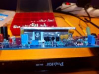
here is some pics of my build. yoy can see why i needed angled aluminium profiles for the vas stage 🙂
Very nice, I am taking my time with mine, I'm in no rush to have another amplifier. haha I am enjoying the process of doing everything slowly, so I don't run out of things to work on. Almost finished one channel of the amp so far.
Will the universal Power Supply Board from the store work well for this project?
Yes. That will work fine. 8x10.000uF 63V will do the job if you og with 2x35-2x40Vac transformer.
Yes. That will work fine. 8x10.000uF 63V will do the job if you og with 2x35-2x40Vac transformer.
Excellent, thank you kindly. I just ordered an Antek 40V 600VA
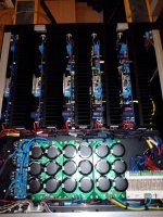
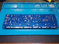
A few pics
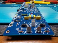
Here are a few pictures, I've gotten further along install all the caps and diodes, still trying to find a VAS HS and one of the mica caps doesn't fit even though it was directly from the BOM.
Here are a few pictures, I've gotten further along install all the caps and diodes, still trying to find a VAS HS and one of the mica caps doesn't fit even though it was directly from the BOM.
Attachments
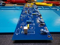
Position of the trimmer pots
I'm getting closer to starting the amp up for the first time, with respect to the trimmer pots. It gives initial values, but it doesn't say what pins this should be between. For example the 200 ohm pot is set to 200 ohms max, and zero between the other side of the wiper.
I'm getting closer to starting the amp up for the first time, with respect to the trimmer pots. It gives initial values, but it doesn't say what pins this should be between. For example the 200 ohm pot is set to 200 ohms max, and zero between the other side of the wiper.
If you are talking R7, the CCS pot, the honey badger board should short the pot wiper to one end. So if the pot wiper loses contact (and they do over the years) the resistance value goes to maximum.
The schematic on build guide shows R7 as a resistor, not a pot, so you'll have to look at the board to see what the layout people did.
The schematic on build guide shows R7 as a resistor, not a pot, so you'll have to look at the board to see what the layout people did.
By looking at the board, two pins will be shorted. Measure between center and the non-shorted pin taking care to install in the correct orientation that you measured.
TJ
TJ
By looking at the board, two pins will be shorted. Measure between center and the non-shorted pin taking care to install in the correct orientation that you measured.
TJ
Perfect, thanks takitaj. From a quick look the traces/pads didn't look shorted. However I didn't actual measure it with a DMM after installing it. I'll do it when I get home.
One of the three pots, doesn't have two pins tied together. I think it's the offset pot. Also another question, what length standoffs have others used? I want to mock it up so that it fits the 4U heatsink when I buy one, which won't be for a long time. The print out with the UMS hole patern doesn't exactly line up with the board either. I measured it and the measurements are bang on, but everything is a little offset with the actual board.
For the one that doesn't have 2 pins tied; set for equal resistance, both sides, to center pin.
I don't know about the UMS spacing. I made my own chassis for the HB. I thought I read that the newer boards were changed to fit UMS. (?)
I would guess 1/4" (6.35mm) spacers would be adequate.
TJ
I don't know about the UMS spacing. I made my own chassis for the HB. I thought I read that the newer boards were changed to fit UMS. (?)
I would guess 1/4" (6.35mm) spacers would be adequate.
TJ
Thanks again, I think it'll come down to a case of "close enough" and the worst case is I'd have to resolder the transistors. They will be a on a bit of an angle.For the one that doesn't have 2 pins tied; set for equal resistance, both sides, to center pin.
I don't know about the UMS spacing. I made my own chassis for the HB. I thought I read that the newer boards were changed to fit UMS. (?)
I would guess 1/4" (6.35mm) spacers would be adequate.
TJ
With the way things are going in Italy, and the record low Canadian dollar, I won't be ordering the Chasis any time soon. At least I have something to build while I wait this all out, j/k lol
Hi I have been using my HB for about 3 yrs now. I'm not sure why Audioson is requiring so much rail capacitance?? I using large can 22000 uF caps per rail. This is on maggies which are a heavy load for an amp. My power supply was scabbed from an older AB amp of 250W/CH. I'm not having any issues. As far as output protection I haven't built it into any of my amps(4). Now I make all my connections powered down always? I do realize that something could go wrong and burn up my speakers but for over 15 years no problem. Besides I run used speakers not worth multi thousands of dollars. b So I'm willing to take the chance.
Got it working
Hello all, I hope everybody is healthy and safe during these trying times. On a positive note, I wanted to update everybody know I got the first channel of my amp working with all your help. Hooked it up to my +-36v limited lab supply. The bias and offset are at 0 mV or close to it without trimming anything. Too good to be true, and I ran some sin waves from the function generator. I still am deciding what to do for my power supply and don’t know if the Italian made chassis would be shipping with the situation going on there, my thoughts are with them at this time.
Hello all, I hope everybody is healthy and safe during these trying times. On a positive note, I wanted to update everybody know I got the first channel of my amp working with all your help. Hooked it up to my +-36v limited lab supply. The bias and offset are at 0 mV or close to it without trimming anything. Too good to be true, and I ran some sin waves from the function generator. I still am deciding what to do for my power supply and don’t know if the Italian made chassis would be shipping with the situation going on there, my thoughts are with them at this time.
Hello. Modushop are producing and shipping as normal. Aggiornamento Corona Virus
But i don't know how the italien DHL/post service and customs are doing these days. You could get the chassis from DIY audiostore if that is a better option.
But i don't know how the italien DHL/post service and customs are doing these days. You could get the chassis from DIY audiostore if that is a better option.
Last edited:
Hello. Modushop are producing and shipping as normal. Aggiornamento Corona Virus
But i don't know how the italien DHL/post service and customs are doing these days. You could get the chassis from DIY audiostore if that is a better option.
Orders placed through the DiyAudioStore are still shipped by us. At the moment the situation here in Italy is VERY confusing as all "non-necessary businesses" are supposed to be closed from 25/3 until 3/4 but they are keeping an eye on the situation and then decide what to do.
We are shipping today and tomorrow for sure but unfortunately I don't know how things are going to change in the next days 🙁
Good luck to you and all at Modushop and all Italians in general!
Despite of the situation, I'd stil order directly at Modushop in order to avoid double customs fees and VAT.
Best regards!
Despite of the situation, I'd stil order directly at Modushop in order to avoid double customs fees and VAT.
Best regards!
Orders placed through the DiyAudioStore are still shipped by us. At the moment the situation here in Italy is VERY confusing as all "non-necessary businesses" are supposed to be closed from 25/3 until 3/4 but they are keeping an eye on the situation and then decide what to do.
We are shipping today and tomorrow for sure but unfortunately I don't know how things are going to change in the next days 🙁
Okei. I wish you guys good luck. it's a nightmare over there.
i have placed all my projects on hold for now. i will be ordering some front panels and heatsinks from modushop when Things og back to "normal" 🙂
Hello all, I am going to use some of the time throughout this lock down to work on my amp. I have received my antek 40V 600 VA transformer. I am looking around to see what primary fuse should be used. I will be running 2ch honey badger, the transformer is 600VA with 2x 40V and 18V and 15V.
What size fuse should I use on the primary, does it need to be slow blow or fast etc? Also what bridge rectifiers should I use? I am looking at the quick connect type that are 200V RPV and 25 amps each, are those ok? For the power supply, what bleeder resistors have you guys used most in the past?
Thanks in advance for any tips I could get.
Whatever power the boards want, the transformer will supply 600 va before overheating in 3 or 4 hours. So 600 va/120vac=5A. You could be generous and give it 6. Toroid transformers surge at turn on pretty badly, so you need a SB. Also a NTC negative temperature coefficient resistor in the AC line after the fuse before transformer primary could make turn on more gentle. GE CL-40 is 6 A steady state rated and 5 ohms cold, should be good. I mount these on cinch type solder terminal strips, available mainly from surplus houses instead of the regular distributors. You could screw it in a couple of holes of a euro style screw terminal strip. The cinch jones can mount with a #6 machine screw or 4 mm, but the euro style strips have tiny holes and require 4-40 screws at least 7/8" long to mount. 2 mm might work, I dont' have any that long.
25 A bridge rectifier should work but you need at least 400 PIV rated to cope with transients caused by A/C motor shutoff. those can go 1300 v on the main, multiply by 1/3 to see effect on the rectifier.
If you put a 250 vac or 330 vac MOS surge surpressor across the AC line (after the fuse or circuit breaker) it can keep those surges down to 500-600 v and cut the size of the pop in your speaker when lightning on the line goes off too. These are blue with a big S on them from US vendors like bournes or GE, green with just the voltage from the orient.
You need to build a light bulb box to put in series with your AC plug for first turn on until everything is working great at 20 W. 100 W incandescent bulb in a socket, series a breaker. I have mine in a grounded steel box to prevent the wire from coming out from under the screw and burning my finger off.
Best source for breakers is surplus houses IMHO, if you can justify the freight charge. I just bought a couple from surplussales.com of NB. I don't know what surplus is available in CAN.
Last edited:
- Home
- Amplifiers
- Solid State
- Honey Badger Build... where to start?