Hey guys, been awhile since i've been here!
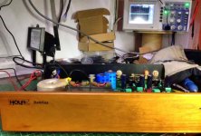
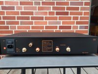
Ran into a strange issue last night while re-connecting my Holfi battriaa phonostage to my toshiba sa7100.
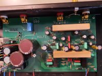
I lost the left channel from the phono input side so i took the cover off and found the whole chassis to be microphonic. If i tap on the metal chassis it creates thumps from the speakers.
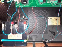
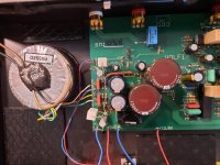
Some kind of grounding issue maybe? The holfi is grounded via mains earth using a spade connection. The toshiba SA7100 has recently had its reservoir caps replaced with Mundorf AG+ (4 pole), so i'm not sure if this has anything to do with it? From what i could gather the transformer centre tap is no longer used with the 4 pole caps.
The turntable (rega RP3) grounds through the phono plugs as far as i know and dosent have a separate ground connection.
Ran into a strange issue last night while re-connecting my Holfi battriaa phonostage to my toshiba sa7100.
I lost the left channel from the phono input side so i took the cover off and found the whole chassis to be microphonic. If i tap on the metal chassis it creates thumps from the speakers.
Some kind of grounding issue maybe? The holfi is grounded via mains earth using a spade connection. The toshiba SA7100 has recently had its reservoir caps replaced with Mundorf AG+ (4 pole), so i'm not sure if this has anything to do with it? From what i could gather the transformer centre tap is no longer used with the 4 pole caps.
The turntable (rega RP3) grounds through the phono plugs as far as i know and dosent have a separate ground connection.
Microphonic chassis could be a sign of RF parasitic oscillation or bad ground connection.
I don't understand how a change of reservoir cap could render a secondary CT no longer needed. You will have to show us the circuit and describe carefully what changes you made.
I don't understand how a change of reservoir cap could render a secondary CT no longer needed. You will have to show us the circuit and describe carefully what changes you made.
The Mundorf AG+ caps are 4 pole, where as the old caps were 2. According to the spec sheet for the caps the ground is not tied to the CT.
 [/url]
That is the only change for the amp.
I've not changed anything else with the phonostage or turntable.
Its running at high gain for a 0.4mv MC cartridge.
Edit: when i mentioned about CT no longer used, i meant it has no direct connection to the ground of the amp (apologies).
That is the only change for the amp.
I've not changed anything else with the phonostage or turntable.
Its running at high gain for a 0.4mv MC cartridge.
Edit: when i mentioned about CT no longer used, i meant it has no direct connection to the ground of the amp (apologies).
Last edited:
OK, the CT is still used but now goes via the cap.
Look for something you changed or forget to reconnect when dismantling and re-assembling for the cap change.
It is just possible that something was relying on the track impedance (which you have now removed) to damp a resonance in the PSU. So-called 'RF snubber' or 'RF blocking' caps may rely on the nearby electrolytics being a bit lossy. Putting 'better' electrolytics in can create new resonances.
On the Toshiba unit i dont have the RF snubber or RF blocking caps as they were not present in the original setup.
Do you think i should add them in?
Here is the tosh schematic for the power section.

The rectifier does have some ceramic caps around it.
Do you think i should add them in?
Here is the tosh schematic for the power section.
The rectifier does have some ceramic caps around it.
Now I am confused. You told me that the CT was unused, then said that it was connected via the cap. Now you show me a diagram which clearly has no secondary CT, but has two caps in series with balancing resistors. What exactly have you done?
Sorry, i should have pasted the whole schematic for the toshiba unit.
The CT is grounded on the tosh unit, which was connected to the negative of the old reservoir caps.
All grounds were tied together across these caps, with bleeder resistors.
The CT is grounded on the tosh unit, which was connected to the negative of the old reservoir caps.
All grounds were tied together across these caps, with bleeder resistors.
Looking at the schematic i found the CT and connected it as per the wiring for the new caps. In the bundle i found 3 connections for the output transistors on each rail, so connected these as per the wiring diagram. All other grounds were connected to the ground main wiring as per the diagram, not the CT.
So the secondary has a CT but the circuit diagram does not show it? I am still confused. A 'grounded' CT would connect to the junction of the series caps, not negative on the caps.
Yes, thats right. Its on the other side of the schematic.

Highlighted is the CT for the transformer.
Highlighted is the CT for the transformer.
OK, but the junction of the reservoir caps should have something connected to it too. Unless they want buzz due to charging pulses, the CT should connect to the cap junction. Then any ground should come from there, not the secondary. However, drawing this wrongly is quite common in commercial circuits; sadly, connecting it wrongly is not as rare as it should be.
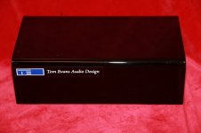
Thanks DF96, i resolved the issue last night, it was nothing to do with the amp.
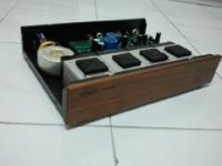
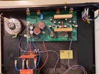
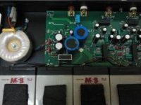
The holfi battriaa i have uses 3 pins at the back to select whether its MC or MM cartridge you are using. These pins are shorted with a small wire, rather than just using a switch. One of the solder joints was slightly loose so i reflowed it and no more feedback from tapping the casing.
Who would have thought!
OK. The next thing I was going to suggest was putting the old caps back in and see if the problem goes away.
Yes i did contemplate that if it didnt work. The mundorf caps have changed the sound quite significantly on the Tosh unit!
are there a schematic diagram available ?
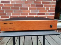
What is the aim of the wooden parts (square edges made of solid wood) - go to the images under
www.avmentor.gr - Reviews: Holfi Batt2riaa phono preamplifier
What is the aim of the wooden parts (square edges made of solid wood) - go to the images under
www.avmentor.gr - Reviews: Holfi Batt2riaa phono preamplifier
Last edited:
here a description and various images of this phono RIAA pre-amplifier (different versions):
http://www.pladespilleren.dk/Anmeldelser-tests/Kontravaegnet 2-2009_Batt2RIAA.htm
https://positive-feedback.com/Issue24/holfi.htm
A good approach is the avoid of switches for select MM and MC - instead this a soldered jumper.
What happen to HOLFI resp. the developer of this devices, Mr. Peter Holstein ?
And who have a schematic diagram ?
Attachments
-
 131462208_1031872470648427_4261752302559313722_n.jpg61.7 KB · Views: 115
 -
 131934418_1031872400648434_1574643694108656817_n.jpg26.3 KB · Views: 89
 -
 2011-010.jpg6.1 KB · Views: 96
 -
 1938131905_2_g.jpg120.7 KB · Views: 110
 -
 2011-011.jpg9 KB · Views: 110
 -
 1938131905_5_g.jpg92.7 KB · Views: 96
 -
 1938131905_4_g.jpg109.8 KB · Views: 115
 -
 1938131905_3_g.jpg155.7 KB · Views: 101
 -
 1938131905_6_g.jpg110.5 KB · Views: 93
 -
 1938131905_7_g.jpg95.3 KB · Views: 89
 -
 1938131905_8_g.jpg90.4 KB · Views: 81
 -
 8522751174_g.jpg110.1 KB · Views: 81
 -
 00001.jpg150.7 KB · Views: 77
 -
 01.jpg160.4 KB · Views: 88
Last edited:
- Home
- Source & Line
- Analogue Source
- Holfi Battriaa strange issue