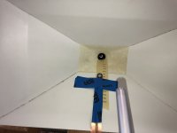
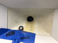
I wanted to measure experimentally the effect of midrange port location on the response of a Unity-like horn. However, I didn’t want to cut holes in my horns, test the result, fill the holes, cut new holes, and repeat. So, I bought a microspeaker whose diameter is similar to the holes I was envisioning, and which is also very thin. DB Unlimited Speakers and Transducers makes a “dynamic micro” speaker, which I bought from Mouser Electronics (part number 497-SM160908-1). I taped the microspeaker to the horn wall at different locations and measured the response. The photos and figures are an attempt to make clear what I did and what I found. Note that microspeaker locations are measured relative to the interface between the compression driver and my horn’s mouth. That is not expected to be an acoustically relevant location, it’s just convenient and reproducible.
The figure with the measurements has two sets of axes (see pdf attachment for a clearer view). The bottom axes show the raw response of the microspeaker when attached to a flat panel, and the response when the microspeaker is 70 mm from the throat of my horn. The upper axes show the measurements taken at various distances from the throat, but each response is first divided by the raw response from the microspeaker on the flat panel.
I wanted to see if I could reliably locate the response notch that results when sound emanating from the midrange port (here simulated by the microspeaker’s output) travels toward the compression driver mounted to the horn’s throat, reflects, and interferes destructively with the response travelling directly from the port to the microphone. The trend in the location of what I think is the notch (identified with a red circle on the upper axes, and labelled according to microspeaker location) is pretty much what would be expected: The notch moves to higher frequency as the microspeaker moves closer to the compression driver. There’s nothing earth-shattering in the results. It’s just a convenient experimental way of trying out different “port” locations without irreversible damage to the horn. I haven’t yet verified that the real midrange ports will behave similarly, but the trend looks reasonable.
Clearly HornResponse and other simulators provide a way of predicting the effect of port location, but 1) these days I don't have enough free time to both simulate and build, 2) the simulations require knowing the true location of the surface from which the sound reflects, and 3) I wanted to measure the behavior in my actual horn, not a simplified model of it. I don't claim that this approach is superior to simulations, it just suits me better at the moment, given the constraints on my speaker building time. I'd be interested to hear of anyone else's results if they try something similar (or if others have done this and I just missed it).
Few
Attachments

I find this highly interesting, and it explains very graphically why the midrange ports on synergy derived designs should be placed as close to the beginning of the horn as possible.
But shouldn't this be in multiway?
I am also wondering if the three way versions would not benefit in just placing the mid/woofers beside the horn. Seems there are certain disadvantages to having extra ports placed further out.
Is there much difference to using 4 ports? I think 2 ports are sort of minimum of what people use, and perhaps 4 ports is more common(?). I understand that this experiment is sort of an oversimplification just to get a slight overview of a general trend, but it would be nice to know.
I have more microspeakers (they're cheap as dirt) so that I can test arrays and see what the spacing does. I figured I'd share what I've seen so far to determine if there's any interest. Thanks for the response; I now know it's useful to at least one person!
I'm not sure I understand your multiway question. My goal is to put one or two midrange drivers through two or four ports in the horn, so I'm trying to find the best location for those ports.
I've seen some examples of woofers placed just outside the horn's mouth and I find that approach attractive as well. That's several steps from where I am at the moment (I'm new to the land of horns) so it's something I ponder abstractly while I work through the concrete questions of where to place, and how to shape, the midrange ports. I cringe at the idea of putting holes into the walls of the horn while fearing they're not in a good location! Fortunately, making the horn parts should go much more quickly the next time around.
Few
Ha! I just had a flash of understanding about your multiway comment. I somehow managed to post the thread in the wrong category. I’m not firing on all cylinders.
Moderators: Could you please move this to the multiway, rather than full-range, category? My apologies for the mistake.
Few
Moderators: Could you please move this to the multiway, rather than full-range, category? My apologies for the mistake.
Few
Elegant and interesting.
For example, when you ~double the distance (50 to 110mm), the frequency of the notch goes down - but it doesn't halve, as I would have expected. That's a helpful finding.
I might borrow this idea 🙂
Have you written about how you made the horn? Is the throat rigid foam that you cut with a hot wire?
For example, when you ~double the distance (50 to 110mm), the frequency of the notch goes down - but it doesn't halve, as I would have expected. That's a helpful finding.
I might borrow this idea 🙂
Have you written about how you made the horn? Is the throat rigid foam that you cut with a hot wire?
By all means borrow the idea! I found it quite easy to implement.
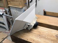
I have not yet written up a description of the construction techniques. In short, I made the throat, which serves as a transition from the compression driver to the flat surfaces of the horn, out of polyurethane. I made a mold and used Tap Plastics two-part polyurethane resin. It worked quite well. The surface has some tiny pores that you can see in the photo, but it's solid once you get more than 1 mm from the surface. In fact, it's solid and dense enough so that I tapped it and used bolts to hold things together.
The flat surfaces of the horn were made using 1/4 inch PVC panels. I kerfed them on a table saw and then heated the kerf with a heat gun so I could bend each panel to the angle needed to flare at the mouth. After bending it, I mounted each panel to a jig that allowed me to run it quite precisely through a bandsaw and create edges with the correct angles without having to fiddle with compound miter angle calculations. I didn't even have to tilt the bandsaw table. I have some photos I can post once I can squeeze in a few spare minutes.
Few
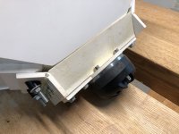
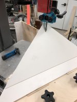
Here are a few photos that might help clarify the bandsaw-based cutting approach I used.
Photo 1: PVC panel mounted on cutting jig and part way through a bandsaw cut.
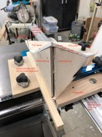
Photo 2: PVC panel after both of its mitered edges have been cut, but still mounted on the jig, which is still on the band saw's sliding table (which I built based on parts purchased from ACCU-SLICE). Magnetic clamps hold a wooden indicator in place on the band saw table so it's easy to line up the cutting jig for the cut. The jig's motion is guided by the aluminum extrusion, not by the wooden indicator.
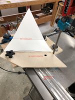
Photo 3: View from the outfeed side of the band saw.
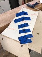
Photo 4: Two panels with edges already cut, positioned on cutting jigs positioned to serve as gluing guides. PVC adhesive (intended for PVC plumbing) creates a strong joint. This photo shows tape holding the joint together. More force can be applied by using hot melt glue to tack small wooden blocks onto each panel near the joint. Clamps can then grip the blocks and squeeze the joint closed. I've learned that applying clear packing tape onto the PVC panel before hot melt gluing the blocks in place makes it easy to remove the blocks without marring the PVC.
Making the two cutting jigs, for the two different size panels, was simplified considerably once I realized that the four vertical walls (two per jig) are identical apart for some quick trimming of their upper edges.
Few
Photo 1: PVC panel mounted on cutting jig and part way through a bandsaw cut.
Photo 2: PVC panel after both of its mitered edges have been cut, but still mounted on the jig, which is still on the band saw's sliding table (which I built based on parts purchased from ACCU-SLICE). Magnetic clamps hold a wooden indicator in place on the band saw table so it's easy to line up the cutting jig for the cut. The jig's motion is guided by the aluminum extrusion, not by the wooden indicator.
Photo 3: View from the outfeed side of the band saw.
Photo 4: Two panels with edges already cut, positioned on cutting jigs positioned to serve as gluing guides. PVC adhesive (intended for PVC plumbing) creates a strong joint. This photo shows tape holding the joint together. More force can be applied by using hot melt glue to tack small wooden blocks onto each panel near the joint. Clamps can then grip the blocks and squeeze the joint closed. I've learned that applying clear packing tape onto the PVC panel before hot melt gluing the blocks in place makes it easy to remove the blocks without marring the PVC.
Making the two cutting jigs, for the two different size panels, was simplified considerably once I realized that the four vertical walls (two per jig) are identical apart for some quick trimming of their upper edges.
Few
Attachments
This is great, if you give the null frequencies as numbers I can work out the distance of the apparent point of reflection inside the compression driver from the throat. It should stay constant for all the measurements if the theory is correct.
Thanks for the expressions of interest.
My data show a bit of scatter, presumably because it was my first attempt at determining if this approach has any merit. I didn’t position the speaker with micron accuracy, so that will contribute significantly to the error bar on the results. Since a few people find the results useful I can do another series of measurements, this time with greater care, and tabulate the null frequencies. Part of my intent when starting this experiment was to work out the location of the source of the reflection in the compression driver, so I’d certainly welcome the assistance.
I’m also interested in trying two speakers near the “corners” of the throat. That will probably add some uncertainty to the microspeaker position measurements but I’d like to know if there are any surprises from two non-holes. Using two ports per midrange is very common so I’ll be surprised if anything odd shows up. Only one way to find out I guess!
I wish the microspeakers had more output in the few hundred Hz realm so I could see if I can measure the low frequency cut-off of the midranges, imposed by the location of the microspeaker along the horn’s axis. My guess is that the signal to noise ratio will be crap below 700 Hz but it won’t take a lot of effort to find out if that’s correct. I want to be careful not to be so preoccupied with the high frequency effects of tap position that I drill holes in the horn and discover that the midranges only work for an octave below the mid-tweeter crossover frequency! (I’m exaggerating for effect....)
Few

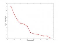
I made another series of measurements, this time more carefully and with more closely spaced microspeaker positions. At some positions the notch was difficult to nail down with confidence. At the 100 mm position it was hopeless. I found that at that location, moving the microspeaker left or right (perpendicular to the axis of the horn) just a mm or two altered the response quite a bit and yielded a detectable peak. The frequency was clearly out of line with the on-axis trend, though, so I just skipped the 100 mm measurement.
A graph of the results is attached, and the raw data are presented below. The left column is the location of the microspeaker in mm, and the right column is the lowest notch frequency in kilohertz.
10 3.42
20 2.97
30 2.64
40 2.46
50 2.41
60 2.28
70 1.92
80 1.85
90 1.83
110 1.73
120 1.73
130 1.62
Few
Attachments
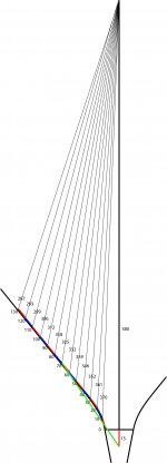
I determined that pretending that the microspeaker lies along the horn's axis was a poor approach. I have now more carefully determined the path length differences between the direct microspeaker-to-microphone paths, and the reflected paths (microspeaker to compression driver to microphone). To simplify some trigonometry, I temporarily established the location of the reflection within the compression driver 15 mm behind the driver's front plane. I have no reason to think that's the correct location but I'm hoping I can figure out where the real plane of reflection is, relative to that 15 mm location. The first figure may not be useful in detail, but maybe it conveys the geometry I'm working with. The microphone is at the top of the figure where the lines converge. The horn's profile is probably obvious, and the microspeaker was moved in 10 mm increments along the wall with the alternating red and blue lines.
From the measured notch frequencies I calculated wavelengths. The data in the table below show, in mm, the path length differences (reflected minus direct) in the first column, and the wavelengths at the notch frequencies in the second column.
54.3000 100.8772
73.4000 116.1616
92.3000 130.6818
108.4000 140.2439
125.4000 143.1535
142.1000 151.3158
159.5000 179.6875
176.5000 186.4865
192.6000 188.5246
226.8000 199.4220
243.0000 199.4220
259.0000 212.9630
I must be doing something stupid because I've not yet extracted a useful calculation of the location of the reflection plane within the compression driver. The notch should appear when the path length difference is half a wavelength, right?
Few
From the measured notch frequencies I calculated wavelengths. The data in the table below show, in mm, the path length differences (reflected minus direct) in the first column, and the wavelengths at the notch frequencies in the second column.
73.4000 116.1616
92.3000 130.6818
108.4000 140.2439
125.4000 143.1535
142.1000 151.3158
159.5000 179.6875
176.5000 186.4865
192.6000 188.5246
226.8000 199.4220
243.0000 199.4220
259.0000 212.9630
I must be doing something stupid because I've not yet extracted a useful calculation of the location of the reflection plane within the compression driver. The notch should appear when the path length difference is half a wavelength, right?
Few
Attachments
I suspect the reflection plane changes with frequency because relatively, lower frequencies won't see the small end of the throat.
There is a much easier way. Just look for the reflection in the time domain. A step or impulse response will show the reflection quite easily. That's what I use. Strangely the reflection point is usually forward of the source location of the compression driver. Not sure why, but it's helpful.
Thanks for the insights.
Using REW I did look at the impulse response, quite quickly I admit, and I didn't see a reflected pulse that I thought would be easier to work with than the notch in the frequency domain. I'll have take another look. Is there any reason stimulating with an impulse, rather than a chirp and then deriving the impulse response, should work any better?
Part of my reason for focusing on the frequency domain was that my main goal was figuring out where the notch would be so that I could match it up with the compression driver's high pass response. That said, I would find it satisfying to figure out where in space the reflection occurs. If that location varies with frequency (thanks for that notion) then perhaps I'll have to rethink how important it is to nail that down. For the purposes of matching to the compression driver, the notch frequency is probably more important.
Few
Use both, you have a powerful tool at your disposal. A derived impulse response is fine. Look at the first 0.5mS and you'll see the reflection in there. I'm not familiar with your SW, but mine will give a dimension associated with the time markers.
I agree REW is a great tool—especially for the price! I’ll take a closer look at the impulse response. I may not have looked at a brief enough time scale.
Few
Few
AllenB:
Does your hose-coupled speaker technique reveal the position-dependence of the low frequency cut-off, as determined by the horn’s local expansion rate? I’d like to find experimentally the sweet spot between the midrange’s high frequency extension (limited by the reflection notch) and its low frequency extension (limited by the expansion rate) before drilling holes.
Few
- Home
- Loudspeakers
- Multi-Way
- Hole-free measurements of the effect of midrange port location in a horn