Just a few PEQs and I had a flat response from 200-3k, so yes it works well. Unfortunately I was only looking for nulls. Results were not dissimilar to yours.
After this I used hornresp. This showed me that the region near/below 200Hz is resonant and interesting. I'm still trying to work it out.
I can gate between the direct arrival, the primary reflection and the mouth diffraction, this has been helpful.
I only have one saved measurement, (but the separate woofer impulse would be interesting to show). Here shows the peak below 200Hz. When I crossed it wanted some extra delay, so I want to work out why. Cross is at 500Hz. I have only one port per speaker at this stage, or maybe I drilled at the wrong place (not by much, I could fix it). Group delay shows the crossover delay and the woofer rolloff. There is a nasty glitch below 2kHz, I think it is some minor damage I did to the throat (easy to fix) or it is the port.
Attachments
Audio-time has been hard to come by, but I'm still fiddling. I made my first FIR filter attempt today, with a miniDSP DRC DA-8. I'm certainly deeply into newbie territory with the FIR filtering game, but it was fun nonetheless. After a little screwing around, I decided that first doing some IIR filtering to get things in the ballpark made the FIR step easier. So I used 4th order Linkwitz-Riley filters to roll off the drivers, and three PEQ filters to flatten their response, in miniDSP to correct things a bit before taking the measurements. I then used the resulting measurements as the basis for FIR filters to correct the magnitude and phase. I've attached the results. I am a few hours into my FIR experience so I'm sure I'm offending the experts... Nonetheless, here are the results I obtained at the mic position I used to create the measurements used as the basis of the FIR filters, and also measurements at a point about 25 degrees off axis horizontally.
My first attempt didn't do anything to account for midrange-tweeter delay differences, so the results were ugly. I found looking at the phase response was the easiest way to monitor the delay mismatch and get close to the flat target response. I had to delay the tweeter about 1.6 ms to get things to match up.
I wish my midrange drivers could reach 300 Hz, instead of dying at 500 Hz, because it's going to make the transition to a pair of 8" woofers more picky than I was envisioning. I have two RS-225 woofers per channel that I'm hoping to integrate. I'm not aiming for high SPLs; I just want to experiment with quasi-point-source behavior from the multi-entrant horn. To keep the woofer ports within a quarter wavelength of the midrange ports at the 500 Hz crossover frequency is going to require 170 mm (7") spacing at the most. If the mids reached 300 Hz the geometry would be easier. Time to rethink midrange driver selection? There aren't a lot of sealed-back choices.
Few
Attachments

You can cross a bit lower by incorporating the LR4 rolloff into your mids FIR and then selecting the -6dB point as your bass LR4 low pass point. You would end up with a crossover point ~425Hz.
A trick I used for time alignment was to use asymmetric electrical crossovers between my mid and high. a higher order electrical crossover (on the high) has more delay than a lower order. This can also be combined with the idea above of using the drivers natural rolloff characteristics as part of the filter.
A trick I used for time alignment was to use asymmetric electrical crossovers between my mid and high. a higher order electrical crossover (on the high) has more delay than a lower order. This can also be combined with the idea above of using the drivers natural rolloff characteristics as part of the filter.
Thanks for the suggestions. I've only begun to explore the woofer-mid crossover options. I'll have to see if I run out of FIR capacity before I'm able to linearize the phase at that junction. Some combination of delay and crossover asymmetry may come in handy. It seems I'm always drawn to trying something like the old Spica TC-50 approach. John Bau used a fourth order Bessel low-pass and first order high pass with the tweeter physically displaced toward the rear by a sloped front baffle.
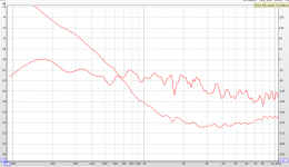
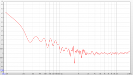
I've found it useful to see measurements in other threads so I'll toss in a few here. The tweeter is a Peerless DFM-2535R00-08 1" compression driver, and the midrange is a Visaton M 10 4" sealed back cone midrange.
Blue: Raw midrange (sloppily mounted to wall of the horn so probably leaky)
Red: Midrange and tweeter after 2 or 3 IIR PEQs were used in the miniDSP to flatten the response. Fourth order Linkwitz-Riley high and low pass filters were also applied at 1200 Hz.
Green: Midrange and tweeter after FIR was applied to flatten the magnitude and phase responses and implement a sixth order Linkwitz-Riley crossover.
The low frequency limit of the midrange is inherent in the driver. Perhaps I can use a crossover point of 425 Hz but I can't help wondering whether life would be simpler if I used a driver that could get down closer to 300 Hz. The quarter wavelength at 425 Hz is about 200 mm (8") which may not be enough of an improvement compared to the 500 Hz I was using as a rough starting point. I've looked at some 5" sealed back drivers but they don't do much better.
Few
Attachments
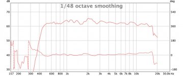
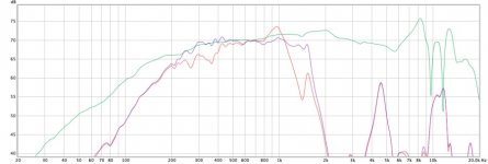
I received a different midrange driver and have done some preliminary tests. It's a LaVoce 4" fullrange driver. Sensitivity is claimed to be 91 dB/watt, so I don't lose anything there. The rubber surround may be less happy about a quasi-compression driver environment than was the corrugated one on the sealed-back driver, but only further testing will tell.
Green: A near field measurement with the driver mounted in a long PVC tube stuffed loosely with rock wool.
Red: Mounted in the horn with a temporary system of PVC pipe to enclose the rear of the speaker.
Purple: A few parametric equalizer adjustments to determine how difficult it would be to end up with a reasonable response and judge the usable bandwidth.
I adjusted the graphs vertically to make them easier to compare so the absolute SPL values are meaningless. Besides, one was a nearfield measurement while the other two were taken about 0.5 m in front of the horn's mouth.
I'm sure the rear volume is not optimized, although I did try a bit larger and a bit smaller to get into the ballpark. In any case, it seems clear that I'll have an easier time reaching the hoped for 300 Hz low frequency extension with this driver.
Few
Attachments
I made a more carefully fabricated enclosure for the LaVoce driver, using two 3 inch PVC caps (one used as a cap, and the other converted to a tube with the same diameter--together they formed an extended cap). I also modified the compression driver mounting plate so I could move the midrange driver a few mm closer to the tweeter, and place its taps less close to the surround of the midrange.
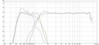
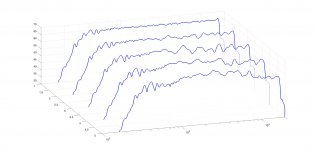
With this newly refined configuration, I made fresh measurements, applied a few parametric equalization fixes, and low-order infinite impulse-mode crossovers using the miniDSP DRC-DA8. I imported the results into FIR creator to generate linear phase responses, with 6th order LR crossover at 1200 Hz, from the midrange and tweeter. I adjusted the tweeter's delay to 1.3 msec using REW to monitor the phase response as I played with the delay. The mic was probably a bit less than 1 m from the mouth of the horn for the measurements I'm showing.
The attached plots show the resulting on-axis magnitude response at the rear of the waterfall plot. Progressing toward the front, the measurements were made 10, 20, 30, and 40 degrees off-axis horizontally. These are iffy measurements made in my acoustically reflective workshop (concrete floor, sheetrock walls and ceiling, not a lot of room) but at least they provide some sense of how things are going.
Few
Attachments
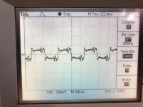
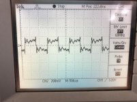
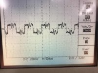
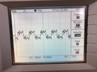
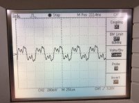
Knowing that indoor measurements, made in a cluttered and reflective environment, are fraught, I was nonetheless curious whether these devices would produce any sign of a recognizable square wave. I surrounded the mic with 3" thick rock wool (in hindsight I'm not at all sure that was helpful), and placed the mic a few cm deep into the mouth of the horn. I then used REW to create square waves with frequencies ranging from 500 Hz to 5000 Hz.
Not surprisingly, the 5000 Hz square waves aren't very square. That's to be expected since the first contributing harmonic would be at 15 kHz and the next is at 25 kHz. The tweeter response starts to dive at 18 kHz so I didn't expect much "squareness."
The other waveforms don't look too bad. I noticed after taking these snapshots that the rockwool panels actually caused some magnitude response peaking around 500 Hz or so, and the mic was located in a less than ideal measurement location (I based the equalization and crossover on ~1 m measurements). Once I refine the speaker, and father winter loosens his grip, I'll look forward to some outside measurements.
The attached images show the response to square waves between 500 Hz and 1000 Hz, and at 5000 Hz. These were all obtained with the mic roughly on-axis.
Few
Attachments

- Home
- Loudspeakers
- Multi-Way
- Hole-free measurements of the effect of midrange port location in a horn