Ok, Had to disassemble somewhat to get proper leads down in there. Starting over....
r1 = 177.5, r2 = 177.8, r3 = 6.2 and r4 = 6.3 ohms
Measuring across r3 = .491vdc, r3 = -.488vdc and rising with temp
Sorry for my miss interpretation. I do appreciate your help.
r1 = 177.5, r2 = 177.8, r3 = 6.2 and r4 = 6.3 ohms
Measuring across r3 = .491vdc, r3 = -.488vdc and rising with temp
Sorry for my miss interpretation. I do appreciate your help.
The R3 and R4 voltages should adjust with VR2, do they? Now measure across the big 5W resistors, should be close to .5VDC. If so biasing is working correctly. The $10,000 question what does the DC offset look like?
VR2 does have effect, but maxed R3 and R4 hovering +/- 5.2vdc. The emitter R's seem to be the issue? The random 4 up top on the H/S hovering in the mid single digit MV range, nowhere near the 1/2 volt expected. Offset for channel A is 43.5mv with bias at 50.8
Dum question but did you replaced the input pair (Can or IC) Q1 ?
Input unbalance can cause output to "drift" ever so slightly...
Input unbalance can cause output to "drift" ever so slightly...
I did, I bought 4 2N2916 sputniks and replaced them in both my amps. Here's some measurements from this amp
A channel, A side
E -.63V
B -22.5MV
C +8.12V
A channel, B side
E -.63V
B -21.1MV
C +8.11V
B channel, A side
E -.63V
B -22.6mv
C +8.27V
B channel, B side
E -.63V
B -21.5mv
C +8.28
The output waveforms from this amp are as clean as my other 16/A (or any of my amps for that matter) ,so it seems like I'm chasing a ghost here. However I can zero my other amps null so this drives me nuts...
I do appreciate your help, think I will just live with it sans any Devine intervention🙂
It's very difficult to offer advice/help when you don't have the "beast" in front you you ...
I'm planning for years to build a clone of this big amp but can't get the info I need
Can you give a hand ?
Nothing to serious just some easy measurements.
I'm planning for years to build a clone of this big amp but can't get the info I need
Can you give a hand ?
Nothing to serious just some easy measurements.
The short answer is yes RS232. If you have been following this thread you understand that I'm a novice and new to posting on this forum although I've been hanging out and reading for over a decade. Terrific info herein for those like me who tinker and learn when time allows. Is this data something that can just be posted or do you PM me so no violations of forum rules are broken?
Regarding cloning this thing, be aware there were several (4 perhaps if memory serves) versions of the Citation 16. LED's, no LEDs, opamp input or can, relay boards are the biggest. Schematic vary as well. I have a brand new set of outputs lying around I may, over time, be willing to part with..
Regarding cloning this thing, be aware there were several (4 perhaps if memory serves) versions of the Citation 16. LED's, no LEDs, opamp input or can, relay boards are the biggest. Schematic vary as well. I have a brand new set of outputs lying around I may, over time, be willing to part with..
Well what I need is actually the dimensions from the boards and the enclosure probably better to do in PM not to clog the thread up with unrelated stuff
Is you and still open ?
Is you and still open ?
PM me and I'll see if I can find it and respond.Well what I need is actually the dimensions from the boards and the enclosure probably better to do in PM not to clog the thread up with unrelated stuff
Is you and still open ?
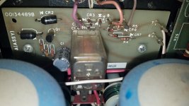
I am the owner of 2 of these monsters, I popped a cover off of one ( a 16A) to take a look around and...... found that, the "protect board" is a hybrid between the 16 ( delayed turn on only) and the 16A with DC sensing protection to the relay. The board I have, has the same assembly# as yours - 00134489B, which seems to be some interim config between the 2. That being said, it seems it has 2 red wires going to the L & R INPUTS from pins 8 & 9, ( Purple & pink wires on top) which, may have some strange input limiting arrangement because there are also small signal diodes near it. I would try to disconnect the wires from that board to the suspect channel and check it for any voltage coming off of the board.
Attachments

Hi Huggygood. Thanks for the response. I fixed the darn thing in the end, more on that in a minute. Regarding the weird relay PCB's, I found two very interesting Service Bulletins from HK, Signed by Len Gaynor. You are correct, boards were being blown up due to input overload. They even provide a troubleshoot procedure to determine. Anyway, SB #208 (5/78) and subsequently SB #209 (8/78) explains it all. Guessing you would find it interesting. I found it poking around HIfiengine, but be sure to look at 16A, not 16 as we are aware of those differences. If you can't find, PM me your address and I'll slip hardcopies in the mail, no sweat. Regarding the fix, it was the 2916's the whole time. Whereas I had sourced and replaced those right up front, they must have been some Chinese junk or otherwise poor quality. I found two Motorola's from a garage sale (retired NASA engineer selling all his stash) and installed those. Bingo, problem solved and untold amount of beating my head against the wall was over. But I leaned something, non the least of which is a community of good and interesting souls here on DIY. Thanks again, take care.
Im Sorry BYTEMEE6666, THANKS TO YOU! See above. As I said, I can send you the SB's...
Take care.
Take care.
Everything is positive and thank you for the offer !Hi Huggygood. Thanks for the response. I fixed the darn thing in the end, more on that in a minute. Regarding the weird relay PCB's, I found two very interesting Service Bulletins from HK, Signed by Len Gaynor. You are correct, boards were being blown up due to input overload. They even provide a troubleshoot procedure to determine. Anyway, SB #208 (5/78) and subsequently SB #209 (8/78) explains it all. Guessing you would find it interesting. I found it poking around HIfiengine, but be sure to look at 16A, not 16 as we are aware of those differences. If you can't find, PM me your address and I'll slip hardcopies in the mail, no sweat. Regarding the fix, it was the 2916's the whole time. Whereas I had sourced and replaced those right up front, they must have been some Chinese junk or otherwise poor quality. I found two Motorola's from a garage sale (retired NASA engineer selling all his stash) and installed those. Bingo, problem solved and untold amount of beating my head against the wall was over. But I leaned something, non the least of which is a community of good and interesting souls here on DIY. Thanks again, take care.
Now you can enjoy

Hi ronoandk
I am a bit perplexed on how you stated that, the trouble did not change when you swapped boards, but you claim it was driver board Q's that needed replacing that fixed the issue. Regardless of that, I am glad you got it fixed. 2N2916's have no "modern day equivalent" , some are still in stock looking at an Octopart search ( link below) , but I am sure they could also be replaced with a matched & thermally coupled pair of NPN's with the right gain and voltage characteristics.
https://octopart.com/search?q=2n2916¤cy=USD&specs=0
I did run into info from a person who ran "Big Sky Audio" that had a shop that specialized in some HK gear, and he left a list of the components he used during his upgrades on the HK 16 / 16A's he serviced. I posted it in this thread below
I can't figure out why they put a "Input limiting circuit" into the protect board like that, as I have seen that in no other amplifier, and it is not present in the final Series A protect board, although they do use a 2 X 2 signal diode config to limit the DC level driving the Op Amp that triggers the Q2 transistor to sink the turn on voltage on Q1 and having it shut off the relay on the last version board.
I have been tinkering around with designing a new AC soft start, DC & thermal protect protect and turn on time delay board for the amps, with MUCH beefier relays and that would also take AC power load off of the main power switch and the 2 - thermal protect devices that currently shut power off of an overheating channel (@90 deg C), and run them through bridged 30 A rated contacts, ( one relay per channel / PS) instead of putting all of that stress on the thermal devices and 1 switch, and also momentarily charging the main PS caps on power up through a 22 ohm Inrush current limiter , 1 for each transformer, ( ICL) until the contacts closed on the AC relays. It would need "remote mounting" off of the chassis plate, since it will be larger than the original protect boards, ( some space is available above the capacitors that I am planning on making brackets for) but should improve / lower resistance through the amp output connections as well, using the same type 30A relay instead of the original 7.5A rated contacts, with a 24VDC trigger.
Posted here are doc's from "Big Sky Audio" dated 4/5/2009, it is a list of what they used to do upgrade / rehab work on a Citation 16 / 16A's aged components.
I
Attachments
Oh, and if you haven't already done so, make sure you replace that "C1" cap on the protect board soon, ( 150uF, 16VDC polar), as if it is the original and shorts, which it it may be already doing, it will pull the base voltage off of Q1 and the relay will never get energized to close. I recommend a Wurth
150uF - 25VDC 10,000 hr @ 105 Deg C cap - https://www.digikey.com/en/products/detail/würth-elektronik/860240475006/5727512
, its a bit higher voltage rating, but VERY high hour and will pass the test of time compared to the original Illinois Capacitor item, and is available at Digikey or Mouser if you order from either of those suppliers. You could also source a Nichi or Ruby, but make sure you get as high an hour rated cap as possible to eliminate / delay future issues.
More schematic study, and more thoughts arise..... Looking at the driver board, C1 is a 100uF - 25V cap, it's the input signal coupling cap just before one base on Q1 ( the transistor you replaced. Putting a polar cap there, allows for a higher voltage/current flow through it with one polarity. Since the positive lead is facing the input jack, in a reverse bias condition, any higher negative AC peaks, or possibly a negative DC voltage will see that cap as a short, get past it because it will act with a much lower resistance, go through R2, which is a 2.7K ohm resistor, and get right to that first base on Q1. Although R1, a 22K ohm resistor is shunting off some voltage to ground before R2, it's still not pulling that signal down a lot, and an overload there would do some damage down the line. The easy "fix", may be, to put those small signal diodes on the input RCA connections, but, IMO, they would do a better job on the connection of the R2 - 1st Base of Q1 junction, and that's where I may connect a limiting diode array of some sort, possibly with a SMD IC with diode arrays in it , on a tiny PCB. I am thinking that a non-polar substitute for the C1 cap would be a better choice, and I will plan to experiment with it, as far as low frequency response, when I get to taking an iron to one of my 2 amps.
As far as the relays being "damaged by the protect circuit" I don't really think that would be the issue as much as, the original relay, only has contacts rated out to 7.5 Amps. That amplifier can, deliver over 8 Amps into a 4 ohm load, and since the load of a loudspeaker is "reactive" instead of being just a plain resistive load, that creates even more stress on contacts. Personally, I think that relays were being damaged by extremes of operations, things like accidentally leaving a preamp volume high while powering the amp on, playing with input connections with the amp on, or, long term use in a "sound reinforcement" application at high power in general. That size relay is common in a lot of smaller, lower powered amps and receivers / Integrated amps, I just think they didn't design a relay rated for the power output, and some headroom for wear and tear.
As far as the relays being "damaged by the protect circuit" I don't really think that would be the issue as much as, the original relay, only has contacts rated out to 7.5 Amps. That amplifier can, deliver over 8 Amps into a 4 ohm load, and since the load of a loudspeaker is "reactive" instead of being just a plain resistive load, that creates even more stress on contacts. Personally, I think that relays were being damaged by extremes of operations, things like accidentally leaving a preamp volume high while powering the amp on, playing with input connections with the amp on, or, long term use in a "sound reinforcement" application at high power in general. That size relay is common in a lot of smaller, lower powered amps and receivers / Integrated amps, I just think they didn't design a relay rated for the power output, and some headroom for wear and tear.
Be sure to check the output devices hfe. By now the old RCA 1B05 are quite weak. Replace all with MJ15024. Use Wakefield 175-6-310P TO-3 Kapton thermal insulators.
Last edited:
- Home
- Amplifiers
- Solid State
- HK Citation 16/A problem