After Planet10 posted the drawing I tried modelling this speaker using MJ King's TL_Offset_Driver MathCad worksheet. I think I must be doing something wrong because the results were terrible (see below). for those familiar with the worksheets I used L = 110.4 cm (a guess), E=0.25, with closed and open ends that are 4.0 x 7.6 cm. I tried no stuffing and then various stuffing densities w/o success.
Any ideas what's wrong?
By comparison Zaph's design (a sealed box) for the HiVi B3N looks like this:
Any ideas what's wrong?
An externally hosted image should be here but it was not working when we last tested it.
By comparison Zaph's design (a sealed box) for the HiVi B3N looks like this:
An externally hosted image should be here but it was not working when we last tested it.
Ok, since I just found a German website/shop with the plans available for viewing/downloading here is the link, thus I attached the plans for your viewing pleasure.
http://www.acoustic-design-online.de/internetshop/shop.htm
Then click the Tangband link.
Dave, fairly accurate measurements!
http://www.acoustic-design-online.de/internetshop/shop.htm
Then click the Tangband link.
Dave, fairly accurate measurements!
Attachments
medical error found
On second thought, the other graph looks like a cardiac patient in even deeper trouble.
On second thought, the other graph looks like a cardiac patient in even deeper trouble.
Hmmm.......
Zaphs tests indicate the NS3 is the best 3" driver for full range use.
The NS3 main advantage is the 5mm one way Xmax and :

compare the low end 3rd harmonic above for the B3S to the NS3 below :

🙂/sreten.
Zaphs tests indicate the NS3 is the best 3" driver for full range use.
The NS3 main advantage is the 5mm one way Xmax and :
compare the low end 3rd harmonic above for the B3S to the NS3 below :
🙂/sreten.
holdent said:After Planet10 posted the drawing I tried modelling this speaker using MJ King's TL_Offset_Driver MathCad worksheet. I think I must be doing something wrong because the results were terrible (see below). for those familiar with the worksheets I used L = 110.4 cm (a guess), E=0.25, with closed and open ends that are 4.0 x 7.6 cm. I tried no stuffing and then various stuffing densities w/o success.
Any ideas what's wrong?
probably not much, since the original design by Udo W asks for a lot of stuffing over the entire length of the line. In addition: which sheets did you use? the old or the current? the current can take into account that the port is on the rear, which might help getting a nicer sim
I have these next to my PC, but then using the W3-315's. I have slightly modified the design, it is a bit deeper (so longer line) and I have left the last quarter unstuffed, this resulted (as hoped for) a nice punchy sounding "ping"
😀

Hi Henk Jan,
Do you have the original plans? What exactly does Herr Udo recommend for stuffing? What material, where, which density and so on. I only have the plain building plans but no background data on the design, unfortunately. On the internet I searched quite extensively but cannot find sites where people actually built these TLs and commented on changing sonics by experimenting with stuffing. Since I really do not like too much damping (I think it destroys dynamics, probably even more in an inefficient driver like the HiVi) today I started with just a tiny bit of sheepwool folded directly behind the driver (approx 3*3*1"). No obvious changes yet: maybe a little more relaxed presentation. However, the entire cabinet packed with wool? I feel a bit hesitant. Please comment!
Do you have the original plans? What exactly does Herr Udo recommend for stuffing? What material, where, which density and so on. I only have the plain building plans but no background data on the design, unfortunately. On the internet I searched quite extensively but cannot find sites where people actually built these TLs and commented on changing sonics by experimenting with stuffing. Since I really do not like too much damping (I think it destroys dynamics, probably even more in an inefficient driver like the HiVi) today I started with just a tiny bit of sheepwool folded directly behind the driver (approx 3*3*1"). No obvious changes yet: maybe a little more relaxed presentation. However, the entire cabinet packed with wool? I feel a bit hesitant. Please comment!
yes I have the plans, send me an
 and I will mail them (when I get back home from vacation next week)
The normal stuffing was BAF (a.k.a. Sonofil) about as dense as it is when you buy it
for other versions of the TischTML, you could search forum.zelfbouwaudio.nl or www.hifi-forum.de
The normal stuffing was BAF (a.k.a. Sonofil) about as dense as it is when you buy it
for other versions of the TischTML, you could search forum.zelfbouwaudio.nl or www.hifi-forum.de
holdent said:After Planet10 posted the drawing I tried modelling this speaker using MJ King's TL_Offset_Driver MathCad worksheet.
Any ideas what's wrong?
Greets!
Apparently nothing. That, or I screwed up in a complementary way using the Hobby HIFI dims (no stuffing)/TB W3-315SC published specs:
GM
Attachments
Ok - I'm getting close to the same sim results as GM using the stuffing density and placement he suggested. (Note to Henkjan - I am using the current worksheets). The sim results both GM and I have posted are probably the "best" and don't account for interactions with back wall and floor.
I went further with the worksheets using Planet10's cab dimensions and did a detailed SPL response calculation to include the back wall and floor with the rear firing port. The best results are acheived when the cab is sitting flat on the floor and as far as possible from the rear wall (at least 1m). Placing them on stands and close to the wall creates deep nulls.
Here's a sample of this design modeled at its best (which is very good) 100m out from the wall and on the floor:
And here it is in a more likely scenario 0.3m from the back wall and 1m up from the floor:
For comparison here's Zaph's sealed box design modeled against the wall 1m up:
And, "the best", against the wall 2m up (which is interesting because Zaph noted that these speakers would sound best "at least 16-18" from the wall" on stands - see http://www.zaphaudio.com/audio-speaker18.html):
Of course these are only modeled results - "in real life your mileage may vary"!
I went further with the worksheets using Planet10's cab dimensions and did a detailed SPL response calculation to include the back wall and floor with the rear firing port. The best results are acheived when the cab is sitting flat on the floor and as far as possible from the rear wall (at least 1m). Placing them on stands and close to the wall creates deep nulls.
Here's a sample of this design modeled at its best (which is very good) 100m out from the wall and on the floor:
An externally hosted image should be here but it was not working when we last tested it.
And here it is in a more likely scenario 0.3m from the back wall and 1m up from the floor:
An externally hosted image should be here but it was not working when we last tested it.
For comparison here's Zaph's sealed box design modeled against the wall 1m up:
An externally hosted image should be here but it was not working when we last tested it.
And, "the best", against the wall 2m up (which is interesting because Zaph noted that these speakers would sound best "at least 16-18" from the wall" on stands - see http://www.zaphaudio.com/audio-speaker18.html):
An externally hosted image should be here but it was not working when we last tested it.
Of course these are only modeled results - "in real life your mileage may vary"!
Greets!
Mine are just simple half space sims using the old freeware PORTED WS since I haven't had the time to get comfortable with the more advanced WSs yet.
I take 'PCTL' to imply sitting on a computer desk near a monitor and other computer accessories, not to mention a big bag of dense damping material (you), so their combined LF/mid-bass/lower mids response will probably look more like a can of worms than a HIFI plot.
That said, I'm kind of partial to this end loaded TL stuffed with my 'best guess' approximation of what it would look like stuffed its entire length with R-19 fiberglass insulation:
L = ~34.404"
CSA = ~13.274"^2
GM
Attachments

So, this small friend is a beast to tame if I interpret the graphs (Holdent, Sreten, GM; thanks for your work) correctly. Currently, I'm still damping them with just this tiny bit of sheep wool directly behind the driver, on stands and close to a wall (ooh horror; Doc will you never learn?) and I must say it doesn't sound bad, at all. Not big, not completely fullrange, not too smooth but still it images, it produces moderate levels of bass (given its size a surprising amount) and it is a real pleasure to listen to acoustic and jazz music. Even a bit of easy pop/rock.
I reckon from the sims, lots of damping may smooth the freq/SPL graph and I'll certainly experiment with the sheep-stuff the coming days but I hate to compromise dynamics. What do the experts recommend/suggest?
Btw. just solved an irritating noise: the holes drilled in the wood for the external inductor were leaking and buzzing with loud bass. A few drops of glue fixed that.
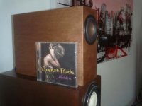
ps. On the pic below you'll see the effect of waxing the veneer and also the kind of music it will not be able to reproduce faithfully (love the CD though).
I reckon from the sims, lots of damping may smooth the freq/SPL graph and I'll certainly experiment with the sheep-stuff the coming days but I hate to compromise dynamics. What do the experts recommend/suggest?
Btw. just solved an irritating noise: the holes drilled in the wood for the external inductor were leaking and buzzing with loud bass. A few drops of glue fixed that.
ps. On the pic below you'll see the effect of waxing the veneer and also the kind of music it will not be able to reproduce faithfully (love the CD though).
Attachments
how about this, interesting comparison between the 3 inchers
http://www.maclementhorn.it/New_Box.htm
Ed
http://www.maclementhorn.it/New_Box.htm
Ed
DocLorren said:So, this small friend is a beast to tame if I interpret the graphs (Holdent, Sreten, GM; thanks for your work) correctly.
I reckon from the sims, lots of damping may smooth the freq/SPL graph............ What do the experts recommend/suggest?
Greets!
You're welcome!
You 'reckon' correctly that with such a small pipe it will take a high stuffing density to smooth it. Really, it needs a relatively huge TQWT to get wide BW smoothness at a low stuffing density (for a pipe), though like a large sealed cab it has little low end excursion limited power handling.
For stuffing, I prefer fiberglass insulation, though Miraflex 25 is a fine 'itchless' substitute.
GM
Hi,
Has anyone simming this tried modelling the effect of what appears
to me to be a severe narrowing of the pipe at the driver point ?
🙂/sreten.
Has anyone simming this tried modelling the effect of what appears
to me to be a severe narrowing of the pipe at the driver point ?
🙂/sreten.
Humm... No I didn't account for this and it took me a moment to figure out what you meant. (You mean that cross-sectional area of the TL is reduced by the relatively large size of driver's magnet - yes?). I know you could do this using the sections worksheet but I'm not sure how to go about this.
It could make a substantial difference and may explain the apparent disconnect between the modeled results and what the speaker seems to sound like to DocLorren.
GM?
It could make a substantial difference and may explain the apparent disconnect between the modeled results and what the speaker seems to sound like to DocLorren.
GM?
sreten said:Hi,
Has anyone simming this tried modelling the effect of what appears
to me to be a severe narrowing of the pipe at the driver point ?
🙂/sreten.
Greets!
Good catch, you're right, in my haste to get them done I didn't even look at the driver. Regardless, this pipe is so small I imagine that all this added constriction does is increase the Q of the 3rd harmonic notch somewhat, making the suck-out a bit worse.
To compensate a bit, don't add any stuffing in the driver area, just add some felt to the inside of the basket legs and cover the magnet.
GM
Another HiVi 3 incher TL
Found another one
http://hxos.altervista.org/u-B3N.html
The link I made before with the translation did not work so try Babelfish or your favorite translator.
Found another one
http://hxos.altervista.org/u-B3N.html
The link I made before with the translation did not work so try Babelfish or your favorite translator.
- Status
- Not open for further replies.
- Home
- Loudspeakers
- Full Range
- HiVi B3S in mini transmission-line