several years ago I ask for successors of old power FET's for the aim of repair vintage solid state amplifiers- go to
https://www.diyaudio.com/community/...28-2sj18-2sk60-2sj26-2sk76-and-2sk180.148801/
Maybe there were helpful advices concerning this in the MJ magazine ? - go to
https://www.diyaudio.com/community/...en-yearly-index-from-1924-2009-wanted.161831/
https://www.diyaudio.com/community/...28-2sj18-2sk60-2sj26-2sk76-and-2sk180.148801/
Maybe there were helpful advices concerning this in the MJ magazine ? - go to
https://www.diyaudio.com/community/...en-yearly-index-from-1924-2009-wanted.161831/

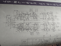
For those, who is not a member at the AK, I have attached JVC amp JM-S7 sch. taken from
https://audiokarma.org/forums/index.php?threads/the-victor-jm-s7-more-v-fet-goodness.1058130/
probably from the MJ mag... Better than nothing...
https://audiokarma.org/forums/index.php?threads/the-victor-jm-s7-more-v-fet-goodness.1058130/
probably from the MJ mag... Better than nothing...
Attachments
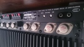
interesting - power FET's (according schematic POWER-jFET's) from NEC - go to the images under
https://www.stereonet.com/forums/topic/304620-eoi-victor-jm-s7-vfet-power-amplifier/
This power amplifier was never to find in a review from a German audio/hifi magazine.
https://www.stereonet.com/forums/topic/304620-eoi-victor-jm-s7-vfet-power-amplifier/
This power amplifier was never to find in a review from a German audio/hifi magazine.
We have a long thread with plenty of d/s for many Japanese V-FET:
https://www.diyaudio.com/community/threads/v-fet-sit-data-sheets.369005/post-6564367
And the "A" stands for some improvement vs originals (like higher voltage...), not worthy
to go for the new part number.
https://www.diyaudio.com/community/threads/v-fet-sit-data-sheets.369005/post-6564367
And the "A" stands for some improvement vs originals (like higher voltage...), not worthy
to go for the new part number.
Talking about V-FET history we should mention the other manufacturers, who were involved
with the V-FET technology. So I will offer here a few remarks related to the russian SITs.
They were late to the V-FET party, developing their first SIT КП801 in the early 1980s.
Before that it was just information, which was well reflected in a good professional Review:
<< Мощные полевые транзисторы с Р-N переходом - Лементуева, Н.В. 1978, Moscow.
Обзоры по электронной технике / ЦНИИ "Электроника" . Сер. 2 . Полупроводниковые
приборы; Вып. 7 >>
This was a technical review with ~80 pages of Japanese V-FET field coverage.
Some electr. college or city libraries in the former USSR will have it.
Those 801 were developed in NEVZ plant in Novosibirsk by request from the nearby sity
of Berdsk Radio plant, which was heavily involved with all types of audio stereo equipment,
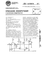
for their use in power amps "Arktur" and "Vega". But, the amp prototype with those SIT
didn't go to production... Some info was trickled out as patents (attach) from the people
who were involved with the development of those SITs and with amp design.
They have also published their ~100 pages development report about SIT usage in audio
amps, which can be found, hopefully, in Moscow, or Novosibirsk, library:
<< Воронцов А. А. и др. Отчет по НИР "Исследование путей создания УНЧ БРЭА в модульном
исполнении на базе кремниевых полевых транзисторов с вертикальной структурой".
Бердск, 1983, 104 с. >> ↴
with the V-FET technology. So I will offer here a few remarks related to the russian SITs.
They were late to the V-FET party, developing their first SIT КП801 in the early 1980s.
Before that it was just information, which was well reflected in a good professional Review:
<< Мощные полевые транзисторы с Р-N переходом - Лементуева, Н.В. 1978, Moscow.
Обзоры по электронной технике / ЦНИИ "Электроника" . Сер. 2 . Полупроводниковые
приборы; Вып. 7 >>
This was a technical review with ~80 pages of Japanese V-FET field coverage.
Some electr. college or city libraries in the former USSR will have it.
Those 801 were developed in NEVZ plant in Novosibirsk by request from the nearby sity
of Berdsk Radio plant, which was heavily involved with all types of audio stereo equipment,
for their use in power amps "Arktur" and "Vega". But, the amp prototype with those SIT
didn't go to production... Some info was trickled out as patents (attach) from the people
who were involved with the development of those SITs and with amp design.
They have also published their ~100 pages development report about SIT usage in audio
amps, which can be found, hopefully, in Moscow, or Novosibirsk, library:
<< Воронцов А. А. и др. Отчет по НИР "Исследование путей создания УНЧ БРЭА в модульном
исполнении на базе кремниевых полевых транзисторов с вертикальной структурой".
Бердск, 1983, 104 с. >> ↴
Attachments
After 801 next SITs were КП802 (40 W -for power supplies) and КП926 (50W, ~16A, ПК-15 - NEVZ
development number).
The problem with those early SITs, be it russian or Yamaha, is big deviation in parameters,
which forced Yamaha to do initial measurement, selection and matching process for their amps
production. Here are a few comments from russian diy folks, who did measurements of their 926:
<< КП926 (1988) 20 pcs, Ids @ 0Vgs: 0,1...1,5A. Rd on: ~300 Ом >>.
To add insult to injury, here is the quote from one of these SITs developers (Google translated):
<< It would be fair to note that all developed SIT and BSIT had a significant drawback - high
cost due to the low yield percentage per chip. This can be explained as follows:
all SIT and BSIT were developed using my technology of chip structure design, which,
as it later turned out, contained gross errors.
According to the specifications, the norm for leakage current between the gate and source
at a voltage of 25 V for the KП926 transistor was set to no more than 1 mA. If the chip had
a defect, but the leakage was less than 1 mA, then it was considered good, although it
was potentially unreliable. >>
Later 926 were updated as КП937, but, practically, the only difference in the parameters
is the lower Ron with the gate current... So, working with these is a lottery... ↴
The other registered SITs are КП942 (ПК-16), only 40W and unproportionally high 10A current -
clearly for switching applications...
Next was КП962 (ПК-25) (10 W, TO-220) SIT.
The last SIT - КП985 was developed ~20y ago, in another plant/city. Again, only 30W and 8A.
Dissappeared from their site a few years ago - no demand. And keep in mind, that
the manufacturer of this part was included into western sanctions... ↴
All transistors we are talking about here have J-FET structure: channel and p-n (junction) gate.
But, depending on the actual geometry, the characteristics will be different:
V-FET / SIT: depletion and triode characteristics
JFET regular: depletion and pentode characteristics
BSIT: enchancement and pentode characteristics
In the same time russians have developed ~2 dozens of BSIT (TO-126, TO-220, TO-3). These
you don't want, don't need - very nonlinear and have no place in the audio (linear) amps.
To study the BSIT characteristics go to the Sanyo d/s for their BSIT GK001T:
https://pdf.datasheetcatalog.com/datasheet2/8/0uuoriu22oacpif7i5e33096ozyy.pdf
Almost all BSIT were sent for production to Makhachkala, Dagestan, and were also discontinued.
Another quote from the developer at NEVZ:
<< NEVZ management transferred the developed SITs for mass-production to the Aleksandrov
Semiconductors Plant.
When the author of these notes arrived at the plant regarding development issues, it turned out
that our former technologist, who was once fired from NEVZ, and then from the Design Dept. at
NEVZ for plagiarism was working at the plant and, together with the Al. plant management,
decided to develop SIT and BSIT himself. Devices developed by this so called technologist in
Aleksandrov, then in Makhachkala and somewhere else, burned like candles.
To increase the percentage of yield of devices suitable for the crystal, he decided to increase
the distance between the gate and source by increasing the etching of silicon and thereby
increasing gate resistance, which reduced the performance of devices by an order of magnitude,
and also caused the appearance of a secondary breakdown with an increase in the frequency
of conversion in the switching PS. In the end russian industry abandoned SIT. >>
For the russian plants involved with the SITs here is the list of their logotips:

↴
But, depending on the actual geometry, the characteristics will be different:
V-FET / SIT: depletion and triode characteristics
JFET regular: depletion and pentode characteristics
BSIT: enchancement and pentode characteristics
In the same time russians have developed ~2 dozens of BSIT (TO-126, TO-220, TO-3). These
you don't want, don't need - very nonlinear and have no place in the audio (linear) amps.
To study the BSIT characteristics go to the Sanyo d/s for their BSIT GK001T:
https://pdf.datasheetcatalog.com/datasheet2/8/0uuoriu22oacpif7i5e33096ozyy.pdf
Almost all BSIT were sent for production to Makhachkala, Dagestan, and were also discontinued.
Another quote from the developer at NEVZ:
<< NEVZ management transferred the developed SITs for mass-production to the Aleksandrov
Semiconductors Plant.
When the author of these notes arrived at the plant regarding development issues, it turned out
that our former technologist, who was once fired from NEVZ, and then from the Design Dept. at
NEVZ for plagiarism was working at the plant and, together with the Al. plant management,
decided to develop SIT and BSIT himself. Devices developed by this so called technologist in
Aleksandrov, then in Makhachkala and somewhere else, burned like candles.
To increase the percentage of yield of devices suitable for the crystal, he decided to increase
the distance between the gate and source by increasing the etching of silicon and thereby
increasing gate resistance, which reduced the performance of devices by an order of magnitude,
and also caused the appearance of a secondary breakdown with an increase in the frequency
of conversion in the switching PS. In the end russian industry abandoned SIT. >>
For the russian plants involved with the SITs here is the list of their logotips:
↴
The late 1970s were the period of change in the SITs story - from audio equipment to industrial,
taken over by Tokin, and RF / microwaves. There were a lot of research in RF SIT published in
that period.Two names worth mentioning here: Toshiba and Mitsubishi. While I do not know any
manufactured RF SIT from Toshiba, Mitsubishi contribution is clearer. The established parts from
them are MFA174, MFA175(?),MFA254. The info about them I expect to be in this magazine:

I didn't find this in my "vicinity", so maybe someone has access to better library...
This "Microwaves" mag in 1982 was renamed as "Microwaves & RF"...
taken over by Tokin, and RF / microwaves. There were a lot of research in RF SIT published in
that period.Two names worth mentioning here: Toshiba and Mitsubishi. While I do not know any
manufactured RF SIT from Toshiba, Mitsubishi contribution is clearer. The established parts from
them are MFA174, MFA175(?),MFA254. The info about them I expect to be in this magazine:
I didn't find this in my "vicinity", so maybe someone has access to better library...
This "Microwaves" mag in 1982 was renamed as "Microwaves & RF"...
By Chance does anyone have a schematic for the Sansui BA-1000.
Working on one over on AK . It was working before i tore into it for a rebuild and stupid me fogot to take vvoltage measurements with the V-fets removed at the output harnes to the V-fet sockets. So now i'm flying blind . I think its ok but not sure.
Working on one over on AK . It was working before i tore into it for a rebuild and stupid me fogot to take vvoltage measurements with the V-fets removed at the output harnes to the V-fet sockets. So now i'm flying blind . I think its ok but not sure.
The only link (with the SM) I can suggest to try is in Japan
(scroll to the bottom):
https://shuminoomochabako.fc2.net/blog-category-36.html
You can politely ask for help with the copies of that SM / schematic pages
in the "contacts" field, and privately, even offering some compensation, at:
https://shuminoomochabako.fc2.net/blog-entry-778.html#cm
(scroll to the bottom):
https://shuminoomochabako.fc2.net/blog-category-36.html
You can politely ask for help with the copies of that SM / schematic pages
in the "contacts" field, and privately, even offering some compensation, at:
https://shuminoomochabako.fc2.net/blog-entry-778.html#cm
Last edited:
Thanks Steve, I was trying to find this blog as I seen it before but could not remember where I had the link.
I tried just now to send a request but you need to add the letters in a window for it to be sent in Japanese. I asked a Fellow memeber whi lives in Japan on AK to help me out.
Lets see where this goes ......fingers crossed
Athanasios
I tried just now to send a request but you need to add the letters in a window for it to be sent in Japanese. I asked a Fellow memeber whi lives in Japan on AK to help me out.
Lets see where this goes ......fingers crossed
Athanasios
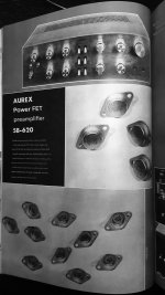
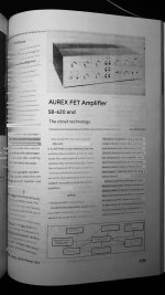
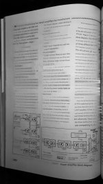
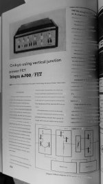
I have finally translated Aurex and Onkyo V-FET amps MJ articles, so here
they are.
It is my understanding, that Toshiba/Aurex components ID system started
like this:
#00 was for the 1973
#10 was for the 1974
#20 was for the 1975 year models, and so on.
First "8" or "9" were for the TOTL models.
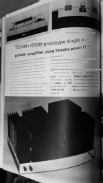
On the Aurex page 159 we can read about models SY/SC-1000, which must
be an even higher level models - statement amplifiers, and SC-1000 -150W
power amp is claimed to have compl. power-FET used. Obviously, that was
prepared for the 1975 year. Another mystery...
they are.
It is my understanding, that Toshiba/Aurex components ID system started
like this:
#00 was for the 1973
#10 was for the 1974
#20 was for the 1975 year models, and so on.
First "8" or "9" were for the TOTL models.
On the Aurex page 159 we can read about models SY/SC-1000, which must
be an even higher level models - statement amplifiers, and SC-1000 -150W
power amp is claimed to have compl. power-FET used. Obviously, that was
prepared for the 1975 year. Another mystery...
Attachments

I remember the first time I heard a Sony V-Fet amp in a highish-end store. It was impressive enough to remember to this day. Don't know if it was necessarily because of the V-Fets though.
It is questioned if the V-Fet's demise might be also be related in that these devices are depletion mode. Perhaps the manner of biasing and protection was found more problematic and costly under circumstances these amps could be blown up in being shorted out, or from other forms of faults. Ultimately it would seem costs would be the primary reasons for their demise, for whatever reason, and not so much negative reviews.
It is questioned if the V-Fet's demise might be also be related in that these devices are depletion mode. Perhaps the manner of biasing and protection was found more problematic and costly under circumstances these amps could be blown up in being shorted out, or from other forms of faults. Ultimately it would seem costs would be the primary reasons for their demise, for whatever reason, and not so much negative reviews.
Cool, I think in MJ 1975 #6 they look at the Sansui BA-1000 that I'm trying to find the schematic for. Do you have that issue?I have finally translated Aurex and Onkyo V-FET amps MJ articles, so here
they are.
It is my understanding, that Toshiba/Aurex components ID system started
like this:
#00 was for the 1973
#10 was for the 1974
#20 was for the 1975 year models, and so on.
First "8" or "9" were for the TOTL models.
On the Aurex page 159 we can read about models SY/SC-1000, which must
be an even higher level models - statement amplifiers, and SC-1000 -150W
power amp is claimed to have compl. power-FET used. Obviously, that was
prepared for the 1975 year. Another mystery...
Just realized you mentioned it in post #19 .
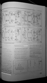
Depends on the very topology: there are only two models with the drains connected to the output (4650/5650) alike a vacuum tube triode amplifier but then in solid state alternative (and with the 'p-channel' opposite), whereas all others have in a conservative manner the sources at the output.Don't know if it was necessarily because of the V-Fets though.
(The Wega 4810 is a black finish 5650.)
- Home
- Amplifiers
- Solid State
- History + archeology = treasures (V-FET)