Missing schematics of Miles Prower’s amp design.
Miles Prower,
This is an old thread, but it still has good information. Unfortunately the discussion doesn't make much sense without the schematics of “your really good design”, the links of which no longer work in the quoted post #9.
Could you post the schematics again please? Or better yet, upload them.
Thanks,
Francois
Last edited:
I downloaded all the info for both your amps a number of years ago, but never got around to doing either. I'm in a position to build Vixen as I have a surplus of both 807s and 1625s, and all the others bits and pieces. Did you ever have any thoughts, given the cathode follower, about a PPP and if there are any changes or additions you'd make to do that? (I have the appropriate OPTs, and power transformers for a PPP so that's covered.)
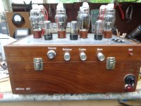
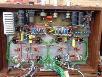
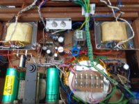
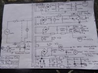
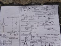
I built an 807 PPP last year, sounds wonderful but it might be a bit complex for first time builders, essentially though it's similar to Miles's amp's, 6SN7 front end and PS with CCS, four 807's, custom OPT's regulated screen grid PSU. Used ESP's preamp using 5532's too. It could be simplyfied though leaving iout some of the extra's. Posted schematics for anyone who's interested. If any other details are needed drop me a line
Andy.
Andy.
Attachments

Last edited:
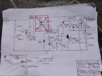
Protects the 807's if any pull too much current if a fault occur, EG like going to gas, spikes etc. If any 807 starts pulling more than 28w then voltage across Rk 10r sense resistor goes up, this triggers a thyristor which in turn energises the relay K2,which in turn cuts the neutral mains supply thus turning the amp off.
Andy.
Andy.
Why not let the thyristor short the B+ ( blowing the fuse in the process ) ?Protects the 807's if any pull too much current if a fault occur, EG like going to gas, spikes etc. If any 807 starts pulling more than 28w then voltage across Rk 10r sense resistor goes up, this triggers a thyristor which in turn energises the relay K2,which in turn cuts the neutral mains supply thus turning the amp off.
Andy.
....Why not let the thyristor short the B+ ( blowing the fuse in the process ) ?
Exactly. There's over 1100u of capacitance in the HT PSU, so, a lot of energy to dump through a thyristor too. This way it's very gentle just switching the power off.Seems needlessly destructive to blow the fuse and stress the power supply.
Andy.
EEEEWWWW!!!!An externally hosted image should be here but it was not working when we last tested it.
http://www.triodedick.com/topcap_807pp/topcap_schema.gif:
Problems:
- Very inferior phase splitter that is not balanced.
- 6SL7s can't properly drive the grids, especially at higher frequencies.
- Inadequate open loop gain.
http://www.dhtrob.com/schemas/afbeeldingen/807pp_verst.GIF
Problems:
- Slight improvement in the phase splitter, but still has problem of unbalanced harmonic distortion.
- Way too much gNFB. You don't need 20db(v) of gNFB for any reasonably well done 807 design. That'll sound very solid statey (and I don't mean good solid state either) and you will likely have stability issues. Given the choice of phase splitter (adequate for the simplest projects and/or where fidelity is not a concern) I'd say that this is an inadequate open loop design and he's trying to compensate with massive gNFB. This is not the way to employ gNFB.
- Way too little open loop gain, and likely sensitivity problems.
In both cases, these designs use cathode bias which gives lots more THD than does fixed bias. (See: STC 807 Application Report) In neither case is there adequate screen voltage regulation, not even including a simple VR tube regulator.
If you want a really good design, then use mine:
Main Schemo
Screen Regulator
Power Supply
Here, I have adequate open loop gain, so that sensitivity will not be a problem under feedback. The phase splitter used here is the vastly superior LTP splitter with a solid state CCS for good AC balance, both in the fundamental and inevitable harmonics. The 807s operate under fixed bias, and the grids have their own drivers so that neither blocking distortion or slew rate limitations become a problem. The front end has a very generous amount of "headroom". Indeed, the OPTs show signs of core saturation before there is any actual clipping. The drivers can push the 807s into Class AB2 transparantly, so that this design actually 30W of output at the onset of core saturation, even though it's rating is 26.5W of Class AB1 power. The screen grid voltage is regulated by an active regulator since screen voltage stability is a key to low distortion operation. Local NFB is included to reduce the effective r(p) of the 807, so that the xfmr primary inductance becomes a larger percentage of r(p). This helps improve bass and serves to get rid of that pentode nastiness. A moderate amount of gNFB further improves bass by reducing Zo, and cleans up what nastiness remains.
This 807 design beats the daylights out of anything I've seen elsewhere on the 'Net. If you're gonna use 'em, then use 'em right and get the most out of them. After all, 807s have some of the best THD figures of any power pentode.
TinyPic pictures no more available.
Is it possible to have them again?
Hello Miles, I was trying to open the 807 amp design files you kindly provided in your 2007-01-23 5:15 pm thread above but the link went dead ? Any other location where the files are still available ? after rave reviews by other DIYers I would like to discover this 807 design. Thanks a lot for your help !
You can get it at Dropbox: VixenHello Miles, I was trying to open the 807 amp design files you kindly provided in your 2007-01-23 5:15 pm thread above but the link went dead ? Any other location where the files are still available ? after rave reviews by other DIYers I would like to discover this 807 design. Thanks a lot for your help !
- Home
- Amplifiers
- Tubes / Valves
- Higher power amps using 807s or 1625s