Miles,
Don't know why I saw this thread so late - my loss.
Your design is probably as good as it comes in this topology, but I have a question. In the diagram attached to your post #9, I see the tail current of the Schmitt phase inverter given as 1,15mA. Is that correct? It means only 0,57mA per 6SL7-half. The load resistor values R11 and R12 are not given there, but I find some difficulty in seeing how such a low Ia can drive the next buffers linearly up to the 80Vpp odd needed for the power stage, unless you use many megohms for their grid resistors.
Then not to rain on any parade, but also kindly allow comment on the emphatic statement that you make regarding 20dB of global NFB being way too much. With due respect, this is bad how? Most tube amplifiers I have seen use at least 20dB, with the classic Leak TL12 using 26dB and the Mullard 520 all of 30dB! These designs are by no means unstable under normal conditions, and about their quality I have heard few quibbles over the years.
I respect the listening experience of yourself and several others, but as as many folks exist finding such amplifiers excellent, it is back to the old question: How subjective are perceptions of inadequate sound, and why is "high" NFB necessarily to blame? (I am not looking at ridiculous figures.)
Regarding damping factor discussed earlier, it has been shown that, depending on the loudspeaker design, little advantage is to be had with figures over 10-13. (This can also be calculated empirically.) Again, with respect, a DF of 4 sounds a trifle low though. It is known, however, that there are pitfalls trying to achieve a high DF by feedback only; the output stage internal impedance should also oblige.
Not to hi-jack the thread away from the topic, but these points did seem relevant.
Regards.

Johan Potgieter said:Your design is probably as good as it comes in this topology, but I have a question. In the diagram attached to your post #9, I see the tail current of the Schmitt phase inverter given as 1,15mA. Is that correct?
Yup.
It means only 0,57mA per 6SL7-half. The load resistor values R11 and R12 are not given there, but I find some difficulty in seeing how such a low Ia can drive the next buffers linearly up to the 80Vpp odd needed for the power stage, unless you use many megohms for their grid resistors.
The load resistors there are 220K. Even though the entire front end tops out at 80Vp-p, the finals will never see a voltage anywhere near that high since the OPTs'll be well into core saturation before then. The actual front end output voltage doesn't go much over 45Vp-p. Given the supposed Ci + Cmiller (sort of a "reverse Miller" since the LTP works into a cathode follower) + Cstray, there is enough current drive to charge up that capacitance at 30KHz. Slewing really isn't such a problem, either sonically or on the o'scope.
Then not to rain on any parade, but also kindly allow comment on the emphatic statement that you make regarding 20dB of global NFB being way too much. With due respect, this is bad how?
At just 12db(v) of gNFB with this design, the sonics were absolutely horrible. Sounded every bit as bad, if not worse, than a MOSFET based solid state design from Circuit City that I bought a few years ago. Got great reviews, and at the time, I thought it sounded pretty good. Since doing the 807 amp, it's sitting in a shed out back where a family of field mice are using it for their home. Getting that down to 4.0db(v) sounded a helluvalot better.
Most tube amplifiers I have seen use at least 20dB, with the classic Leak TL12 using 26dB and the Mullard 520 all of 30dB! These designs are by no means unstable under normal conditions, and about their quality I have heard few quibbles over the years.
Can't vouch for those particular designs. Perhaps they were compensating for a poor open loop design? Better numbers for the marketing department? Maybe they'd sound even better with less gNFB?
I respect the listening experience of yourself and several others, but as as many folks exist finding such amplifiers excellent, it is back to the old question: How subjective are perceptions of inadequate sound, and why is "high" NFB necessarily to blame? (I am not looking at ridiculous figures.)
Probably very subjective, but, then again, isn't listening a subjective experience? If it were a case of "one size fits all" we could publish that ultimate solution for everyone and shut down these forums, couldn't we? As for NFB, it's been my experience that BJTs can stand a whole bunch, MOSFETs not quite so much, and VTs even less. That's assuming, of course, that attention was paid to the open loop design, and that you're not using NFB to hide something nasty. As to why, who knows?
Regarding damping factor discussed earlier, it has been shown that, depending on the loudspeaker design, little advantage is to be had with figures over 10-13. (This can also be calculated empirically.) Again, with respect, a DF of 4 sounds a trifle low though. It is known, however, that there are pitfalls trying to achieve a high DF by feedback only; the output stage internal impedance should also oblige.
It's a design trade-off, gain something here; lose something there. Works just fine with the speeks I have. Gives bass with wall-shaking wallop, but doesn't appear to have any underdamped sloppiness. Since I ran the amp for a month with no feedback at all, I'm quite familiar with how that sounds. May not work so swell with other brands. You really shouldn't need sky-high damping factors unless you're using poorly designed speeks, or something like subwoofers that were designed for use with SS amps that have very high damping factors.
Thanks for comprehensive reply, Miles.
Your remarks regarding open loop frequency characteristics and "NFB-to-hide-something" are of course not only true, but often overlooked!
But that was not the problem with the mentioned amplifiers. In fact, the Williamson was one of the cleanest amplifiers there was, and all had maintained open loop gain/low phase angle to comfortably beyond 20 KHz.
As for listening tests to determine what you want, absolutely! It is your (the client's) money. But to determine whether a design is "blameless", well ........ With all the conflicting comments often uttered about the same amplifier, for whose taste must I design? (And all those guys out there writing up "test" results in magazines; when last did they have their ears tested?)
Regards.
Johan Potgieter said:But that was not the problem with the mentioned amplifiers. In fact, the Williamson was one of the cleanest amplifiers there was, and all had maintained open loop gain/low phase angle to comfortably beyond 20 KHz.
Who knows? Appealing to the lowest common denominator by offending the fewest sensibilities? In cases like this, I figure the best thing is variable gNFB. That way, you can max it for impressive numbers for the marketing dept. to have something to brag about, and each listener can decide what sounds best for them. Of course, that means another knob on the panel, and that much less "set it and forget it", and marketing doesn't like that.
Still makes one wonder why they didn't at least try it, even if as an option.
The Carey 845 based monoblocks had a variable NFB control on them. It ranged from 0 to 15db of feedback if I remember correctly. I always like them with a small amount of feedback applied, this was with Spendor sp 1/2 speakers I think...
Isaac
Isaac
I have built several amplifiers with variable feedback controls. I built a P-P KT88 amp with variable global feedback, 0 to 12db. That amp moved from user to users house (I loaned it out a lot) until one day it didn't come home (sold). I inquired about the use of the feedback knob and found that preferences ranged from zero feedback to full feedback. The zero feedback users tended to be older people who had some experience with tube amps. The max feedback users tended to be younger SS amp owners who preferred house rattling bass. I am sure that the speakers and musical tastes had a lot to do with the setting of the knob. One of the borrowers asked me to mod his Cary P-P KT88 amp to add the knob.
My latest SE amp has adjustable cathode feedback, 0 to 6db in the output stage. It also has switchable triode or UL mode. I tend to use zero feedback in triode unless I am cranking the amp to the edge of clipping where I will turn the feedback up a little. UL mode seems to benefit from a little feedback regardless of the vloume level or the speaker choice. This is just my personal choice, yours may (no will) be different.
My latest SE amp has adjustable cathode feedback, 0 to 6db in the output stage. It also has switchable triode or UL mode. I tend to use zero feedback in triode unless I am cranking the amp to the edge of clipping where I will turn the feedback up a little. UL mode seems to benefit from a little feedback regardless of the vloume level or the speaker choice. This is just my personal choice, yours may (no will) be different.
tubelab.com said:I inquired about the use of the feedback knob and found that preferences ranged from zero feedback to full feedback. The zero feedback users tended to be older people who had some experience with tube amps. The max feedback users tended to be younger SS amp owners who preferred house rattling bass.
That lines up with what I've been saying: too much gNFB makes for a "solid statie" sound. That's the main reason that I didn't connect any feedback for a month of listening open loop. I thought that SS amp I had sounded pretty good since there was no other point of reference. Even then, it took awhile to identify what flaws needed gNFB to fix.
I'm having a slight back-order delay on the output xfmr & one other piece of iron, so it will be about another week before I get all the parts. I did get the oak framed base (9x15), brass-anodized aluminum already prepped though:

I've kept up on the feedback discussion, so perhaps I could consider a pot in the feedback line as well, to compare performance. I could start with 100k for R35, then add a 250k linear pot in series with it at the OPT end, and see what happens, probably the best sound with the max at 350 ohms.
Incidentally, as I had previously thought, there is no such thing as RG-75 unless I'm mistaken, it's probably just an RG-6 variant, as it will also have the number 75 on it (for impedance), most likely.
http://www.zianet.com/ebear/coaxlist.html
If I were to add a cap for performance tests, is it correct to assume that it would be in series with the coax line, at the other end, going into the cathode of the 6J5 (not in parallel with the 2k cathode resistor)? And what value range would probably be in the ballpark, for example if one used non-coaxial braided-shielded copper wire?
I do have a scope, but that's something I'm rusty on so far, and would have to spend a few days when I have time off from my day job to get a handle on what to look for. 🙂
Miles Prower said:Who knows? Appealing to the lowest common denominator by offending the fewest sensibilities?
No, Miles, it is quite more scientific than that - has been for the past 50+ years. And why variable NFB has not been offered as an option all these years - surely you can work that out? Demand perhaps and necessity?
A design is optimised and sold as such. NFB is not just a matter of twiddling a separate pot like a volume control - something like a "niceness control", in the words of Douglas Self. (This seemed to be the direction of the previous several posts, if I read correctly.)
I would wonder very kindly and respectfully (please note that) why in the case of hearing preferences, the factor of different preferences/hearing characteristics appears to be a forbidden subject? As I asked previously: For whose taste must I as a designer design? If you like/prefer something, by all means! (to repeat yet again). But let us just differentiate between that and elevating such preferences to scientific principle/necessity. Again, do I have to belabour this point?
You also denegrate semiconductor amplifiers per se. Again, respectfully, the experience of others (and of designers and of preference) appears to disagree with you. Here I would be more kind; what have you listened to? I can point out some questionable designs, but can one denigrate the use of something because there is abuse?
But I am off topic. Nevertheless I believe these are real considerations; I believe the point has been made. I will now bow out of this line of thought; back to subject.
Regards.
1625 Tube Amplifier
For frank754 ... just cruising th internet and saw you request for a 1625 amp. I built one from scratch 3 years ago ... has TDA1524 IC for the preamp ... so not a pure tube amp. It works great and I love it. Sounds like you have already selected a design.
For frank754 ... just cruising th internet and saw you request for a 1625 amp. I built one from scratch 3 years ago ... has TDA1524 IC for the preamp ... so not a pure tube amp. It works great and I love it. Sounds like you have already selected a design.
Thanks James, yes, I will be trying Miles' design (for the most part, just a few tweaks to the power supply and some 12v tubes rather than the 807, same specs).-- 1625's 12SN7GT's & 12SL7GT, with the regulated bias supply (6AQ5A, 6CB6A, 0C5), and a 5U4GB PS.
I already have all the parts & tubes, just waiting on the iron which is back-ordered.
I've already put together a few smaller amps (6V6 based, etc), and this will be my biggest project so far. He seems to have been very meticulous in design, not playing up the "power" aspect (as these tubes can be driven a lot higher), but rather going for excellence in sound. There are several plans on the web for 807's, most lack in refinement.
Once it's done, I've got a couple of new super 10" Audio Nirvana full-range speakers still in the box, and also have a very old HH Scott FM mono tube tuner coming from Ebay.
Should be a nice "listen" once it's all set up, and I'll try running both speakers in parallel at 4 watts.
I'm finally underway on this project, and have a quick question:
I notice that this PS uses a full-wave bridge and provides B- voltage on the "left" leg coming from the full wave bridge. I've already drilled the chassis and am using a 5U4GB for the "right" leg, (into the choke and to the vpp & 150vdc

Would there be any major concerns if I used two 1N4007's as the "left leg" of the PS supplying the B- (Vkk) voltage?
The Vkk supplies low-current cathode voltage for the 6SN7 driving the 807's, and R3 is 10k, but not any plate current for any tubes.
Like this:

This would avoid a second tube, for which I don't have enough filament amperage, and also I'd like to keep the 5U4 for the main B+ of the PS for the "slow warming effect" and avoid a standby switch.
I presume also that I should probably use a 47uF cap for C2 to prolong the life of the tube.
Thanks
I notice that this PS uses a full-wave bridge and provides B- voltage on the "left" leg coming from the full wave bridge. I've already drilled the chassis and am using a 5U4GB for the "right" leg, (into the choke and to the vpp & 150vdc
Would there be any major concerns if I used two 1N4007's as the "left leg" of the PS supplying the B- (Vkk) voltage?
The Vkk supplies low-current cathode voltage for the 6SN7 driving the 807's, and R3 is 10k, but not any plate current for any tubes.
Like this:
This would avoid a second tube, for which I don't have enough filament amperage, and also I'd like to keep the 5U4 for the main B+ of the PS for the "slow warming effect" and avoid a standby switch.
I presume also that I should probably use a 47uF cap for C2 to prolong the life of the tube.
Thanks
Frank 754,
There is no problem using silicon diodes as you have drawn. It in fact saves you two tubes, as the cathodes are no longer tied. But I would regard the 1N4007's inverse voltage spec as a little low for comfort. If I am correct the transformer is a 350-0-350V type (don't see it here). The maximum inverse voltage across the diode in this case would be 2(Vp), or 2 x 495 = 990V. The 1N4007 is rated at 1000V.PIV. That allows too small a margin for spikes, variation in mains voltage, etc. I do not know what is available near you, but would look for a 1.3 - 1.5KV diode - as you say current is insignificant; they are mostly 1A or higher.
C2 of 47uF would be advisable. Then, so that you are not misunderstanding, the 5U4 as I know it is a directly heated rectifier; not much of a slow warming effect there - barely enough to not overstress the filter input capacitor. If you need to avoid a peak charging effect before the amplifier tubes have warmed up (also cathode stripping to a degree) you would still need some way of delaying h.t. on for about >13 sec. A 5V4 or at slightly lower current capability, 5AR5/GZ34 would be a better option - but you apparently already have a 5U4.
frank754 said:Would there be any major concerns if I used two 1N4007's as the "left leg" of the PS supplying the B- (Vkk) voltage?
The Vkk supplies low-current cathode voltage for the 6SN7 driving the 807's, and R3 is 10k, but not any plate current for any tubes.
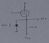
I'm afraid that there is a concern here. The negative rail, being solid state, is going to come up very fast. When it does, the 6SN7 drivers will still be cold, and you're gonna hit the cathodes with 300V. The Vhk rating (heater positive) of that type is specced at 100V. I don't know how much of that they can take without a flash-over. Of course this was not a problem with the Vixen design since that one is wired specifically to allow for heater preheating before you hit it with the HV.
My current project uses a very similar PS (SS negative rail + 5U4GB positive rail) however, this design includes regulated heater DC and that PS is floating, with no connection to the DC neutral. This being done to prevent the problem of H-K breakdown when the negative rail comes up.
Here's another solution to the problem (attached). Here, use a 56V / 0.5W Zener. This will clamp the cathode to a safe voltage until the 6SN7 warms up. Once it's warm and drawing current, the Zener will drop out since the bias for the finals is ~22.5Vdc.
Attachments
OK thanks, Johan & Miles, as far as the xfmr goes, it's a 300-0-300 not a 350-0-350, but will look for higher rated diodes (than the 1N4007's). But am considering a 6X4 now (see below).
For 600v the combined RMS should be only around 850v though.
The Zener "soft start" idea is another good option, which I overlooked. Short of that I could still put in a standby switch for the HV, since all the tubes are on a separate filament transformer except the 6J5, 6CB6 and 6AQ5 (the preamp, and the ones in the bias regulator circuit).
The third option which I like, and would keep the unit "all-tube" would be to add another tube. I have tried to avoid another octal on the chassis with making it too crowded (and also I don't have enough 5v filament amps for two 5v rectifier tubes), but I've just been thinking, how about using a 7-pin 6X4 tube instead of diodes, for the "left leg" B- ?
The 6X4 is rated at 1250 PIV, and can handle a bit above 75ma of load per plate at 300-325v RMS using a capacitor input filter.
For sake of mock-up, I put it in the front & center, but haven't drilled yet. I guess I could put another octal there if need be, as I hadn't considered that spot before, and it's just to the left of the 12SN7.
I've done very little underside wiring as of yet.
frank754 said:OK thanks, Johan & Miles, as far as the xfmr goes, it's a 300-0-300 not a 350-0-350, but will look for higher rated diodes (than the 1N4007's). But am considering a 6X4 now (see below).
How is that going to work? The 6X4 has a common cathode and separate plates. You can't wire it for negative volts unless you connect it as a half wave. If you do that, then you'll need a different negative rail ripple filter since you're cutting the ripple frequency in half, and making the filter half as effective.
I was considering using it as half-wave, but also wondering how it would affect the usability (and result) of the Vkk voltage, and how it would affect the audio as half-wave. Was just doing some research as we speak. So thanks for the quick feedback, Miles.
Noting also, that on the negative rail you were suggesting an R3 of 10k 10w rather than another choke for that side.
There aren't too many tubes with separate cathodes, with the notable exception of the 6BY5 (of which I have none in stock), and a few others at higher filament voltages, and those seem to not be able to take the HV at such a high level.
Also, using two 6X4's would probably be overkill and a waste of transformer heat, as well as requiring two more sockets, not to mention the voltage drop.
Also wondering, if I did use it as a half wave, though it has a cathode separate from the filament, would using the same filament supply voltage as I will for the 6J5, 6AQ5A and 6CB6A create any malfeasance as far as bleedover distortion (or worse) from having the direct AC HV at the cathode (that nearby) and using the same 6.3v filament supply?
Before abandoning this approach and going back to the diode method for the negative rail, are there any dual triodes (for example) with separate cathodes (6SN7 ?) I could use as a rectifier for this negative side, ignoring the grids (or strapping them to the cathodes) and just using them as rectifiers? (seems like this type of circuit is a rare breed for tube aficionados and even when done, usually suggest a third filament supply.)
Probably best to scrap this idea and just go back to the diode plan. 🙂
Miles is correct regarding the heater-cathode voltage, with an admirable solution. Sorry, I did not see that one (I did not have the circuit in front of me then).
Half-wave for bias is used here and there but then with about no load current, i.e. one could use high resistor/capacitor values. I have not seen it lately because of the convenience of si-diodes.
Your thought of using dual triodes as rectifiers is a nifty one, but again the maximum heater-cathode voltage rating is ruling this out. I have not seen the peak inverse voltage of triodes specified, but as said, a no-go for the former reason. (In days of yore when no adeuqate si-diodes were available, I once had to use three 5V heater windings for three GZ34s in a bridge!)
Miles (if you are around)
OK, I finally have it 95% wired and ready to do a thorough circuit check (the Vixen design as a monoblock using 1625's, 12SN7 and 12SL7 JAN tubes, 6J5 metal tube pre-amp, 6AQ5A, 6CB6A, and 0C2 requlator circuit, a 5U4GB for the + rail, and diodes for the - rail), with the 2 transistor/3 diode tail for the 12SL7.
On the feedback circuit, I'm not clear which line on the OPT you have the resistor & coax wired to. I have terminal posts for both the 3.5 and 8 ohm taps (for 2 spkrs in parallel or 1 speaker), but there are also 16, 250 & 500 ohm taps on the 1650G, my guess is the 8 ohm tap. Also, I might try tubelab's idea of variable feedback, perhaps a 500k pot instead of the 330k resistor, how much wattage would this pot need to be and would placement be very critical (i.e., as close to the OPT lead as possible with a very short wire going to it and the coax from the pot to the 6J5?), with the shield grounded only at the 6J5 end, of course.
I made the plate stopper coil/resistor assemblies under the chassis soldered between 2 lugs of a terminal strip and then have thick auto primary wire going to the plate caps. I used bare #18 copper wire and they turned out a bit longer (maybe 20% or so less than 1uH), should this be ok?
I will have to order the 56v Zeners from Allied, to protect the 12SN7 from the Vkk with the filaments cold. In the mean time, can I just temporarily put in a standby switch to stop the Vkk from getting to this one place in the circuit, all other HV lines coming up normally from the 5U4 side?
For the filament supply for the 6AQ5A & 6CB6A, I had to use a separate one from the other tubes. I only had left the main 6.3vct line from the main PT that was unused. I connected this to these filaments, and ran your C5 to ground and R8 to the 150vdc to the center tap. Can I also power the 6J5 filament with this setup, or do I need another filament transformer just for the 6J5, or can I add another resistor to compensate if need be?
As for the main tubes' 12.6v filament supply, I'm just using the AC so far, not the whole regulated deal, and I haven't done anything with the center tap so far, will probably need to put a voltage divider on that as well to raise it up. Other than that, if all goes well, I should have it up & running soon.
Well, thanks for the info, will let you know how it goes. I've been a lot more into ham radio lately and this was my much delayed "last" project (at least for this year) regarding audio.
frank754 said:Miles (if you are around)
On the feedback circuit, I'm not clear which line on the OPT you have the resistor & coax wired to. I have terminal posts for both the 3.5 and 8 ohm taps (for 2 spkrs in parallel or 1 speaker), but there are also 16, 250 & 500 ohm taps on the 1650G, my guess is the 8 ohm tap. Also, I might try tubelab's idea of variable feedback, perhaps a 500k pot instead of the 330k resistor, how much wattage would this pot need to be and would placement be very critical (i.e., as close to the OPT lead as possible with a very short wire going to it and the coax from the pot to the 6J5?), with the shield grounded only at the 6J5 end, of course.
The gNFB is taken from the 8R tap of the OPT since I'm running 8R speeks. If you want to try variable feedback, a conventional 24mm pot will do nicely. This should be wired at the 6J5 end, and not at the OPT end. Ground the coax shield at the 6J5, but not at the OPT.
I made the plate stopper coil/resistor assemblies under the chassis soldered between 2 lugs of a terminal strip and then have thick auto primary wire going to the plate caps. I used bare #18 copper wire and they turned out a bit longer (maybe 20% or so less than 1uH), should this be ok?
Give it a try and see. The coil dimensions should be OK. As for the placement, if that doesn't work out you can always move them.
I will have to order the 56v Zeners from Allied, to protect the 12SN7 from the Vkk with the filaments cold. In the mean time, can I just temporarily put in a standby switch to stop the Vkk from getting to this one place in the circuit, all other HV lines coming up normally from the 5U4 side?
Don't get over eager there. Trying to disconnect the negative rail will leave both the 6SN7s and the finals with no operating bias. That's an open invitation to poof something. Wait for those Zeners before trying to power up.
For the filament supply for the 6AQ5A & 6CB6A, I had to use a separate one from the other tubes. I only had left the main 6.3vct line from the main PT that was unused. I connected this to these filaments, and ran your C5 to ground and R8 to the 150vdc to the center tap. Can I also power the 6J5 filament with this setup, or do I need another filament transformer just for the 6J5, or can I add another resistor to compensate if need be?
The 6J5 has a 90V H-K rating and won't take 150V at its heater, so don't run it off the same heater tap as the voltage regulator tubes. It would be better to connect a 20R / 5W resistor in series with the heater and run it off the 12.6V heater supply. Even better would be to split that resistor into two, 10R sections and put one in series with each end of the 6J5 heater to maintain balance for possible noise reduction.
As for the main tubes' 12.6v filament supply, I'm just using the AC so far, not the whole regulated deal, and I haven't done anything with the center tap so far, will probably need to put a voltage divider on that as well to raise it up. Other than that, if all goes well, I should have it up & running soon.
If you do that, keep an eye on that Vhk of the 6SN7s, that'll be the weak point so far as that goes.
- Home
- Amplifiers
- Tubes / Valves
- Higher power amps using 807s or 1625s