I would like to understand this further. How exactly do current mirrors and constant current sources avoid power supply noise and ripple from getting on the signal?
see Walt Jung's article:
https://pdfs.semanticscholar.org/204a/38f2d10afc4c05f56009a8997120126e981a.pdf
A current mirror is made of two transistors connected in such a way, as to force the currents flowing in both transistors to be equal, irrespective of applied voltage. Therefore, any current change due to power supply imperfections, is equally shared between the two transistors, thereby, cancelling the effect of these imperfections. For this cancellation to be accurate and effective certain conditions must be met with regard to the differential pair. These must operate in such a way such that their collector modulated current component is equal for all signal values. Under these idealised conditions, only the signal current component appears at the output from the current mirror.
A properly biased and compensated current source should not allow its standing current to be modulated by supply voltage changes. Such current modulation is due to a bijunction transistor's output characteristic. The output current, while heavily dependent on base current, it is also, but to a far less degree, dependent on the voltage applied between the base and collector.
An amplifier's input stage is fed power through the output of a current source. A constant current, means the input differential pair will work against each other, with one losing current, while the other one taking it. This swinging of current from one transistor to the other, only depends on signal and current source output current; the power supply does not affect it. Again, these ideal conditions require certain conditions to be met.
The power supply imperfections can reach the input and the output of the input stage through unwanted naturally occurring capacitances, inductances and resistances. Capacitance arises as a direct consequence of electric fields, inductances arise as a direct consequence of electronic currents setting up magnetic fields around them, and resistance arises as a result that anything can conduct electrons to a certain degree.
Last edited:

Thanks Jackinnj and edbarx!
Dotnek, you will also find books by Doulas Self do a great deal of explaining well worth the investment and they are not overtly mathematical....
Dotnek, you will also find books by Doulas Self do a great deal of explaining well worth the investment and they are not overtly mathematical....
Thanks for the explanations and references!
edbarx---that seems logical for the input and driver stages, but since the output devices are directly connected to the power supply, it seems to me that they won't be afforded these cancellation properties.
Also, if modern opamp-driven preamps are SOOOO good at PSSR, why use any regulation at all?
Of course, I could just sh**-can the whole regulation idea and just get one o' these to solve ALL my problems!!😛
Power Plus – DH Labs Silver Sonic
My post is not exhaustive about the subject, there is more to it. As you rightly write, regulation of the power supply itself, also contributes to a cleaner output. If you reread my descriptive post, you will also read that current sources should be properly protected agains power supply imperfections. Two of these methods rely on driving a current source using a regulated voltage. These are i) using a Zener Diode to supply a current source, and ii) using a cascode, so that, a current source would 'see' a constant voltage. The output stage's unwanted effects can be reduced using negative feedback, and making sure, the instantaneous rail voltages never drop below a certain level, to allow enough Vbc during peak output voltages.
As rightly written earlier in this thread, a series pass voltage regulator, makes use of a BJT's output characteristic, which is a positive slope with a low gradient. The low gradient means, the output is still dependent on Vcb. However, given enough negative feedback, and enough rail voltages, this should be mitigated using adequate negative feedback. The fact of including the power stage in the negative feedback loop, is indicative this practice helps. Otherwise, why would anyone include a potentially unstable sub-circuit to complicate matters for no advantage? Power stages are emitter followers with a theoretical near unity gain; in reality, they still are non-linear, even though, theory states they have a near unity gain.
As rightly written earlier in this thread, a series pass voltage regulator, makes use of a BJT's output characteristic, which is a positive slope with a low gradient. The low gradient means, the output is still dependent on Vcb. However, given enough negative feedback, and enough rail voltages, this should be mitigated using adequate negative feedback. The fact of including the power stage in the negative feedback loop, is indicative this practice helps. Otherwise, why would anyone include a potentially unstable sub-circuit to complicate matters for no advantage? Power stages are emitter followers with a theoretical near unity gain; in reality, they still are non-linear, even though, theory states they have a near unity gain.
A current mirror is made of two transistors connected in such a way, as to force the currents flowing in both transistors to be equal, irrespective of applied voltage. Therefore, any current change due to power supply imperfections, is equally shared between the two transistors, thereby, cancelling the effect of these imperfections.
Yes, but any circuit like a current source or current mirror generates intrinsic noise and that is stochastic, so not cancelled in a current mirror.
Jan
Stochastic thermal noise can be mitigated, but not completely, due to its statistical nature. Such a noise arises from the random motion and distribution of free electrons. However, and this is why, due to the huge number of electrons involved even with extremely small currents, there is always a degree of cancellation. For better cancellation, a bigger number of electrons is necessary. In fact, some differential input stages try to reduce random noise using up to four transistors per input.
Last edited:
Some anecdotal evidence, just to brighten up this amusingly theoretical discussion 🙂
All the commercial power amps regulating the output stage i have heard sound distinctly different. Regulation seems to improve a lot of perceived sonic attributes but it certainly does not make for an amp to sound very dynamic, on the contrary. If this characteristic is very important i would stay away from regulation.
All the commercial power amps regulating the output stage i have heard sound distinctly different. Regulation seems to improve a lot of perceived sonic attributes but it certainly does not make for an amp to sound very dynamic, on the contrary. If this characteristic is very important i would stay away from regulation.
A non-regulated supply not only has mains ripple but also all kinds of noise and junk coming in through the mains and the mains transformer.
I really doubt high power regulators have a sufficient bandwidth to stop RF noise coming through the mains. Appropriately wound chokes are a lot more suitable.
All the commercial power amps regulating the output stage i have heard sound distinctly different.
You are describing my regulated Linn Amp (which is eligible for Social Security here in the States) -- it is quite civil but lacking in dynamics.
You are describing my regulated Linn Amp (which is eligible for Social Security here in the States) -- it is quite civil but lacking in dynamics.
Maybe we should wait Jan Didden make good design of voltage regulator for power amplifier as good as his Super Regulator.
Walt Jung recently share his design of very low noise voltage reference. It is cheap and much lower noise than typical IC voltage reference.
The Voltage Regulator spec. we expect:
- Low Drop
- High PSRR at least until 100kHz.
- Low output impedance.
- Can loaded by transient current without too much ripple.
....since the output devices are directly connected to the power supply, it seems to me that they won't be afforded these cancellation properties.
We usually wire the output as emitter follower. As it says on the tin, it follows the input signal, not the power supply. Not perfectly-- in tube we observe that a CF's PSRR is about Mu. What is a BJT's Mu? Usually well over a thousand.
I simmed something. Follower with a NO-signal DC bias, and 4V of crap on the supply rail. It is important to note that a signal source is never Zero impedance. I added 50 Ohms. This could be a very stiff driver (opamp) or it could be a global NFB loop reducing effective driver impedance very-low.
The simmed number is 4V peak crap is reduced over 1,000:1 for 0.002,5V peak crap at the output. An emitter follower can be VERY effective at ignoring supply variation. (There are various collector-output schemes and most of these have the same property if properly implemented. Collectors are NOT voltage sensitive.)
Also, if modern opamp-driven preamps are SOOOO good at PSSR, why use any regulation at all?
Indeed. Mostly, I think, because as long as you are playing with chips, more chips in the power supply seems fitting. I've often run opamps in critical systems with just C-R-C filtering. If you need every last bit of voltage output, then you run the opamps AT their MAX rating, and now a regulator may save your bacon when the wall-outlet runs high. IMHO that's like driving too close to the edge of the road and asking the guardrail to keep you from going over the edge.
Attachments
That's just over 60dB. At 1kHz. So using that 4V example as supply ripple, that will give 2.5mV at the output. If the output signal is say 25V that's -80dB. So your THD+N will never be better than -80dB and limited by the supply. Go to 10k and you loose another 20dB. Not pretty.
Jan
Jan
Simple emitter follower is not good enough, as Jan said. You should see Jan's Super Regulator. Replace op-amp with discrete op-amp that capable high voltage. It is almost make another amplifier for different purpose.
I think you just made a VERY good point for a regulated supply. AS Jan points out, that 2.5mV "peak crap" is only 80 db below a 25 volt output (~75 watts/8Ω). Not particularly good. But what about when you are only driving room listening level? Maybe 5 volts, ~ 3 watts. Then your crap is only ~-66 db below----pretty bad, actually!!I simmed something. Follower with a NO-signal DC bias, and 4V of crap on the supply rail. It is important to note that a signal source is never Zero impedance. I added 50 Ohms. This could be a very stiff driver (opamp) or it could be a global NFB loop reducing effective driver impedance very-low. The simmed number is 4V peak crap is reduced over 1,000:1 for 0.002,5V peak crap at the output. An emitter follower can be VERY effective at ignoring supply variation.
(speaking hypothetically here) Interesting point about dynamics through a regulated supply... I wonder how many regulators have tens of thousands of uF of capacitors AFTER the series pass element (as well as before) so that the power amp can still draw HUGE INSTANTANEOUS currents directly ....
Not many I'll warrant!
I suspect you might get some benefit if you pay attention to the above.
By which time you'll have so much C on your power supply you could do away with the regulator anyway!!
Not many I'll warrant!
I suspect you might get some benefit if you pay attention to the above.
By which time you'll have so much C on your power supply you could do away with the regulator anyway!!
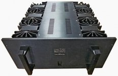
The Mark Levinson ML-2 power amp has regulated power supplies. Have a look at the photo below. ML-2 has six enormous heatsinks. One for left channel pull-up, one for left pull-down, one for right channel pull-up, one for right pull-down, one for positive supply rail regulator, and one for negative supply rail regulator.
ML-2 is revered for the beautiful sound it produces. It's one of the most prized collectible amplifiers of all time.
To me it's a demonstration that voltage regulation doesn't always ruin the sound.
_
ML-2 is revered for the beautiful sound it produces. It's one of the most prized collectible amplifiers of all time.
To me it's a demonstration that voltage regulation doesn't always ruin the sound.
_
Attachments
Last edited:
Used to have one of those too. It also suffered from a very muted top end, thanks in part to an aggressive low pass filter end and a ridiculously low input impedance. So wish Linn would stick to turntables.You are describing my regulated Linn Amp (which is eligible for Social Security here in the States) -- it is quite civil but lacking in dynamics.
That is a solid argument. Sadly, never had one of those.To me it's a demonstration that voltage regulation doesn't always ruin the sound.
Perhaps the most elaborate example of a regulator i was familiar with was in a Naim NAP250 and the poor dynamics stereotype fitted it perfectly.
- Status
- Not open for further replies.
- Home
- Amplifiers
- Power Supplies
- High Voltage Regulated Power Supplies for Power Amplifiers