before potting you can test the opt.....then when everything works out good, you can start potting those OPT's.....your traffo maker should be able to do that for you...
your traffo maker should be able to do that for you...
testing the opt or potting it?
either way it can't be done realiably. I must test the opt in action with the gu81m and it would be very expensive to have the toroidals sent back for potting.
installation in my chassis is difficult to so I will have to work with the opt "outside" the amp before final installation.
what would be a good way to dessicate the amp? airtight storage with silicagel for a few days?
i mean potting it......
in that case you will have to pot it yourself....if you can find a suitable container and epoxy compounds, you can diy....
in that case you will have to pot it yourself....if you can find a suitable container and epoxy compounds, you can diy....
epoxy I have plenty (I used to make my own carbon fiber parts for my motorcycle)
Container, will a plastic toroidal container suffice?
I have a picture of some testing on the driver.
I need a x100 probe to proceed further. The scope at 50v/div clips.
The 6bl7 can really take a beating. I made all sorts of mistake working on it and it is still kicking!
Container, will a plastic toroidal container suffice?
I have a picture of some testing on the driver.
I need a x100 probe to proceed further. The scope at 50v/div clips.
The 6bl7 can really take a beating. I made all sorts of mistake working on it and it is still kicking!
looking good.....
so you have experience with carbon fibre, that will even make a good encapsulant for your opt'S....
so you have experience with carbon fibre, that will even make a good encapsulant for your opt'S....
really? do you think a carbon fiber encapsulation is worth exploring? I can easily make one with a stamp of the container as template.
ok. I will.
I can either wrap an existing container in CF or make an entire new container. What do you think?
I can either wrap an existing container in CF or make an entire new container. What do you think?
I will install 4kv GDTs in clear glass tube envelopes
I'm not so sure that is the answer. I worked with lower voltage GDT's about 20 years ago to protect line powered radio equipment mounted in remote locations where the power source was less than ideal and lightning strikes were guaranteed.
We used devices made by CP Claire and Siemens. The GDT functions much like a neon bulb or a 0B2 regulator tube. It has a speciallized gas mixture inside so that once the strike voltage is reached an arc will occur causing the voltage across the device to drop. The ones made to operate directly across the power lines can carry a huge amount of current for one half cycle, about 16mS on 60 Hz. The arc should extinguish when the line voltage crosses through zero.
We were getting field failures where the GDT had melted and in some cases the arc continued after the GDT ceased to exist destroying the PC board and most of the device. I could not duplicate this destruction in the lab.....until I duplicated the field conditions where the device could be powered by several hundred feet of wire between the device and the power company distribution transformer. The same power source was also operating several kilowatts of sodium vapor lamps.
After a consultation with the GDT vendors engineers, we learned that the GDT must experience a zero crossing of its supply voltage in order to extinguish. This must come before the critical temperature is reached where the device will auto-strike on the next half cycle. In our case the sodium vapor lamps and their solid state ballasts were poluting the power source such that there was no clear zero crossing, and the GDT never extinguished.
I believe that you may be in the same situation with a constant DC voltage across the GDT. Maybe the devices have improved in the past 20 years, I don't know. I would check with the vendor, or perform some experiments before risking a possible catastrophic event.
ok. I will.
I can either wrap an existing container in CF or make an entire new container. What do you think?
good plan...😀
and his is exactly why I love this forum!
your input is much appreciated. I will send an email to epcos and ask.
What would you suggest as a more reliable approach? Tube based device maybe?
I need something which is available at a reasonable price.
Thanks!
your input is much appreciated. I will send an email to epcos and ask.
What would you suggest as a more reliable approach? Tube based device maybe?
I need something which is available at a reasonable price.
Thanks!
Damage from the opt
An externally hosted image should be here but it was not working when we last tested it.
Inviato dal mio GT-I9001 con Tapatalk 2
Maybe the sharp edges of the soldering joint are a starting point for
partial discharge and lead to the flashover.
regards
The Core is large and the transformer heavy. What would be an inexpensive way of dessicating and potting the OPT?
Thanks
Not inexpensive but the way transformer companys do it:
Drying in the oven, then put into a tank where vacuum is applied and
potted in this tank under vacuum...
regards
Isn't there a tube which could somehow replace the gdts?
Inviato dal mio GT-I9001 con Tapatalk 2
Inviato dal mio GT-I9001 con Tapatalk 2
No ideas?
Are there an other, none tube, devices which might work better than gdts?
Inviato dal mio ASUS Transformer Pad TF300TG con Tapatalk 2
Are there an other, none tube, devices which might work better than gdts?
Inviato dal mio ASUS Transformer Pad TF300TG con Tapatalk 2
What about using a high power thyratron operated so that the peak voltage across the opt exceeds maximum inverse voltage?
Something like this perhaps.... if i were to find a cheap lot could it be a solution?
http://www.ebay.com/itm/TG1-2-5-4-T...pt=Vintage_Electronics_R2&hash=item3a68ef134f
Inviato dal mio ASUS Transformer Pad TF300TG con Tapatalk 2
Something like this perhaps.... if i were to find a cheap lot could it be a solution?
http://www.ebay.com/itm/TG1-2-5-4-T...pt=Vintage_Electronics_R2&hash=item3a68ef134f
Inviato dal mio ASUS Transformer Pad TF300TG con Tapatalk 2
Alex,
Unfortunately a thyratron works much like a GDT, in fact it IS a GDT with a control grid. Once the gas inside the thyratron ionizes the only way to shut it off is to remove the plate voltage. There were some speciallized devices that could be shut off, but I don't remember any that could work at this power level.
I have thought about this issue quite a bit and I haven't got an answer.
I experimented with several ways to avoid frying the OPT in the case of operating an amplifier without a load. The worst case is a guitar amp operating at full crank when the speaker fails to an open.
I had best luck with GDT's, MOV devices and even Transorb diodes, but they were all attached to the secondary to clamp the voltage at about twice the expected maximum. These work on mid powered amps, but they just fry in a 300 watt guitar amp.
Your amp should have enough power to melt about any type of clamp device. Any device attached to the primary of the OPT will try to clamp the B+ which has enormous stored energy, and it will discharge that energy through the OPT.
thanks for your post!
Unfortunately the fact that you haven't found a solution makes it almost impossible for me to stumble across one by myself.
I found a good lot of thyratrons (the model I linke to above). a hefty piece of glass!
My concern is that what i witnessed is not a random event (allbeit caused by an solvable issue) but may be related to the interaction between the amp and the huge inductance of the opt. If this is the case I think a solution may be required for the amp to reliably work in the future.
My though is the following:
two tg1 - 2,5/4 are placed across the opt primary section. The insulation for the opt will be upgraded to above 4kv. In case of a spike the reverse voltage barrier is punctured and the thyratron turns on. The problem would be how to turn the device off and remove the bypass.
I am trying to read as much as I can and found this..
http://www2.l-3com.com/edd/pdfs/crowbarapplicationnote.6.pdf
seems an intteresting read.
What about a string of thyratron + resistor + ptc thermistor to rapidly quench the current draw and lift the clamp?
Inviato dal mio ASUS Transformer Pad TF300TG con Tapatalk 2
Inviato dal mio ASUS Transformer Pad TF300TG con Tapatalk 2
while waiting for opt repair, thyratron and some other stuff I have worked on the driver board.
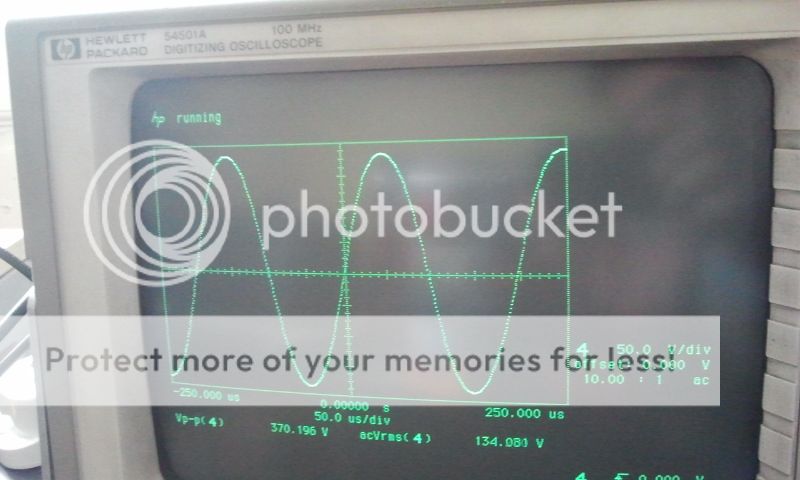
I cannot measure beyond 390vpp as the scope clips so I connected the probe to the common cathodes of a single 6bl7 tube. Adjusting persistence and display i managed to get a clear view at the sine wave (while cranking the signal beyond the 390v barrier)
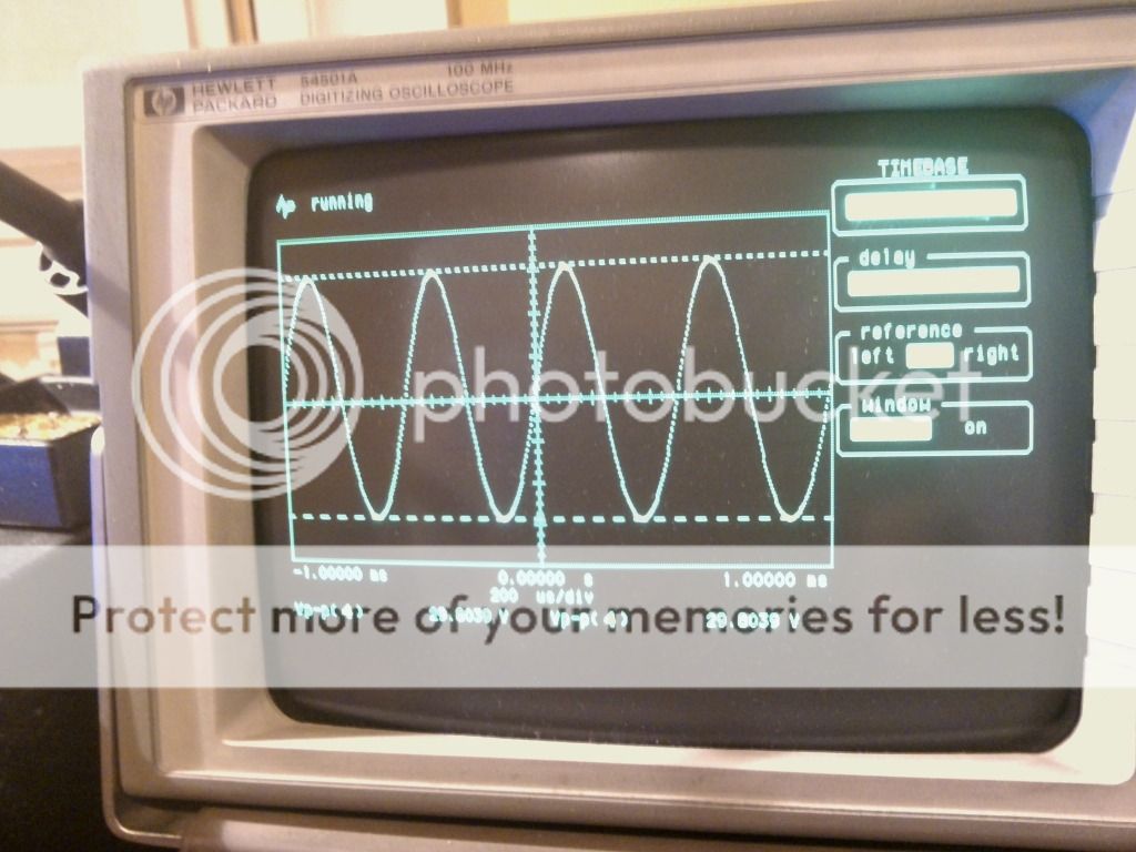
if ccs are set differently the peaks are not alligned to the voltage markers.
Unfortunately I cannot tell what vpp is produced but it *should be almost 430/450 vpp.
Sine was ok but square was bad.

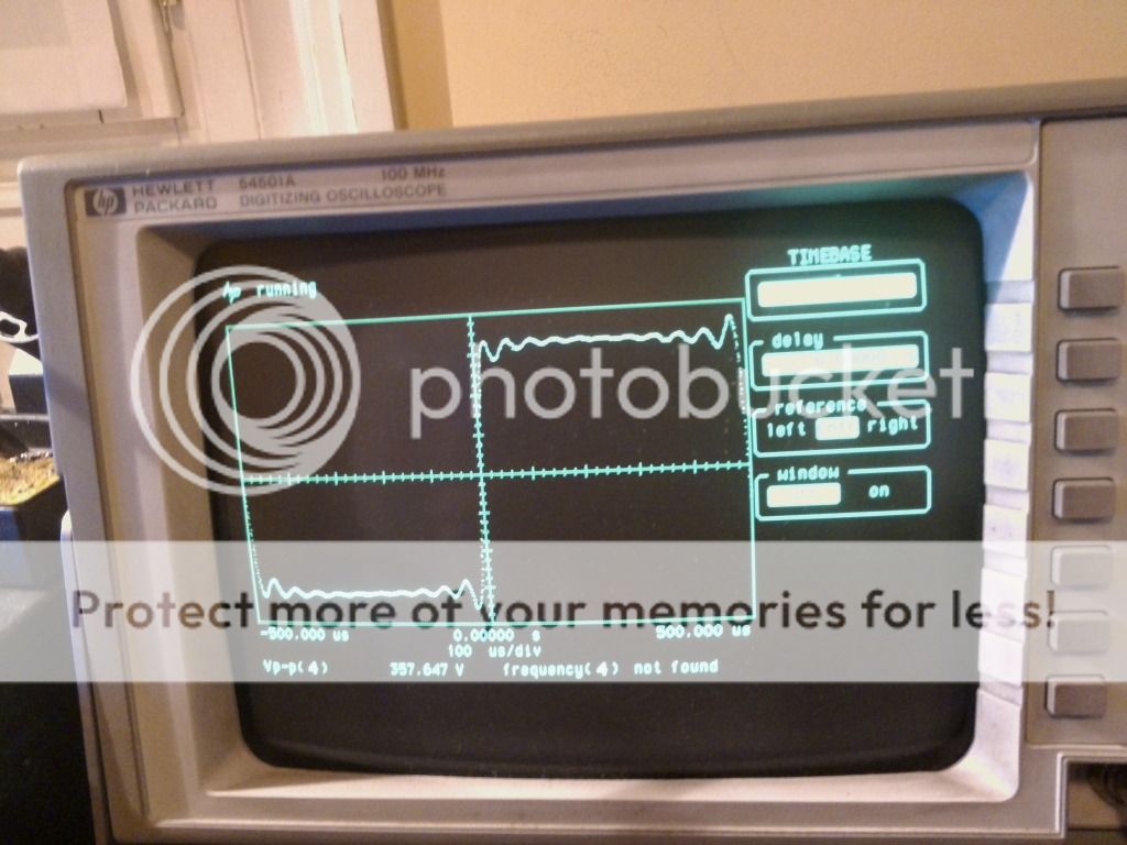
without fb, high voltage swing and possibly a not high enough probe impedance this may be acceptable but it seems to me almost every anomaly one can find in a square wave test is infact there!
Observations?
I cannot measure beyond 390vpp as the scope clips so I connected the probe to the common cathodes of a single 6bl7 tube. Adjusting persistence and display i managed to get a clear view at the sine wave (while cranking the signal beyond the 390v barrier)
if ccs are set differently the peaks are not alligned to the voltage markers.
Unfortunately I cannot tell what vpp is produced but it *should be almost 430/450 vpp.
Sine was ok but square was bad.
without fb, high voltage swing and possibly a not high enough probe impedance this may be acceptable but it seems to me almost every anomaly one can find in a square wave test is infact there!
Observations?
- Status
- Not open for further replies.
- Home
- Amplifiers
- Tubes / Valves
- High voltage driver for AB2 operation GU81m tubes