

Right now, nothing.
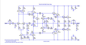
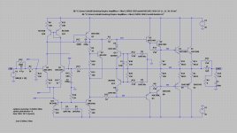
SOA protection is missing the resistors that go from Re to the bases of the protection transistors. Sensible values which limit the short circuit current to reasonable levels make R22 and R23 too small and run the peak output current way too high. So it needs a little rethinking. Q6 needs something to limit its current when Q9 activates.
R8 is a bad idea for soaking up voltage. Passive resistor stuck in there just degrades the high frequency CMRR of the diff pair. Either cascode it or use the 1845. Q7 needs a base stopper to prevent latch up.
CFP in half the driver stage in one side and not the other is weird, but probably no reason why it won’t work. Using the same size driver/predriver also a bit weird, as you usually want to use a predriver that is faster than the driver. Which way? Tough call. MJE340/50 is probably strong enough for +/-50 with sustained beta outputs. Personally I’d go bigger there, but you could just as easily go smaller on the predriver.
Cdom looks too big to me, but I haven‘t fully analyzed it.
The current source of the VAS has a Miller capacitance which affects its base current. This goes against the very idea of using a constant current source. However, I stand to be corrected.
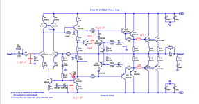
I didn’t see that there. I just saw that 330 pF on the VAS side which is probably too high. And the 10k resistor in the LTP tail just soaking up voltage and effectively adding more capacitance to the LTP tail’s current source.
Looks like attempts were being made to be different for the sake of being different. But to quote Lloyd in one of the Yellowstone episodes “Different never works”. In that particular case, he was right.
Looks like attempts were being made to be different for the sake of being different. But to quote Lloyd in one of the Yellowstone episodes “Different never works”. In that particular case, he was right.
Wg-ski sir thanks for the suggestions.I didn’t see that there. I just saw that 330 pF on the VAS side which is probably too high. And the 10k resistor in the LTP tail just soaking up voltage and effectively adding more capacitance to the LTP tail’s current source.
Looks like attempts were being made to be different for the sake of being different. But to quote Lloyd in one of the Yellowstone episodes “Different never works”. In that particular case, he was right.
Wg-ski sir i will post here the asc file of amplifier then you modify it and then post the schematic here.
You have great experience about amp. I want to see that how you make this amp more accurate & perfect then i will build it.
Last edited:
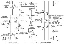
Take some ideas from Douglas Self's blameless amplifier. The biasing of the current sources can be improved.
I have douglas self and cordell pdf books. I will try to study them.Take some ideas from Douglas Self's blameless amplifier. The biasing of the current sources can be improved.
This is the Blameless.Take some ideas from Douglas Self's blameless amplifier. The biasing of the current sources can be improved.
It is an amplifier that works good.
Attachments
Guess you might not be aware - that the machine I use for general internet duties is not CAD-capable. It just the way I keep critical stuff from getting corrupted without buying subscriptions or new equipment every time I turn around. If you want me to take a look at something, post a screen shot or a PDF that this thing can open (not every pdf works).
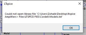
I opend his asc, here is a screenshot.post a screen shot or a PDF that this thing can open (not every pdf works).
Attachments
.model KSC1845 NPN (
+IS = 52.5f NF = 1.0 BF = 408 VAF = 150
+ISE = 4f NE = 1.5 IKF = 0.8
+RC = 0.28 RE = 0.15 RB = 40 RBM = 4.0 IRB = 250u
+ISC = 1.9p NR = 1.0 BR = 15 VAR = 20 NC = 1.3
+CJC = 4.8p VJC = 0.6 MJC = 0.29 TF = 149p VTF = 4.0
+CJE = 26.5p VJE = 0.73 MJE = 0.162
+RCO = 105 VO = 2.2 GAMMA = 1.6u QCO = 2p QUASIMOD = 1
+EG = 1.181 TR = 10n XTB = 1.728 )
You still haven’t hooked up the protection circuit transistors yet. They will rob a little open loop gain when you get within 50% of their trip point. Simulations will bear this out. Not the end of the world, but something to be aware of. And unless hooked up, do nothing to prevent blowouts.
Unless you isolate the bases of Q8 and 12, it will latch to the rail when it clips. It won’t SIMULATE that way, but it will.
Is running the predriver at 6x the idle current of the driver intentional? You can make a case for running them isothermal - but be aware of the need for a heat sink. TO-126’s at 2 watts will leave a nice little blister on your finger (and you don’t get your money for nothing).
- Home
- Amplifiers
- Solid State
- High quality class AB 100 watt amp