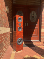
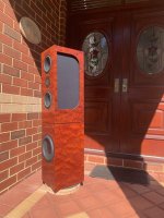
Funny, back when I worked in tech, I poked around a big Gibson's display at a MS event, entered a draw & got a call on my way home that I'd won a similar guitar. 😎 I sold if off a couple months later because I never got any work done: spent too much time messing with it at my computer with the several digital effects boxes that came with it.My wife was quizzing me on what the full up cost for this latest project is likely to be, including the eventual woofer/subwoofer cabinet upgrade to twin SB34NRXL's per side.... She has decided that she might be in the mood for a new guitar.
https://www.gibson.com/en-US/p/Electric-Guitar/Les-Paul-Supreme/Fireburst
View attachment 1418650
I guess I have no grounds to object...
Cool that she's a guitar player! 👍
Congratulations, Jim!
My wife was inspired to get a piano during the lockdowns in Melbourne, Australia, which only lasted 262 out of 18 months.
Warning- the following attachment contains depictions of restrictions of liberty that some readers may find disturbing.
I suggest Melbournians in Victoria (not Florida) avoid opening this attachment.

Reference:
https://www.publish.csiro.au/ma/pdf/MA22002
My wife was inspired to get a piano during the lockdowns in Melbourne, Australia, which only lasted 262 out of 18 months.
Warning- the following attachment contains depictions of restrictions of liberty that some readers may find disturbing.
I suggest Melbournians in Victoria (not Florida) avoid opening this attachment.
Reference:
https://www.publish.csiro.au/ma/pdf/MA22002
This is the only electric guitar my wife has ever owned. We bought it in 1990 (along with a Fender Twin Reverb tube amp) to celebrate graduating from university, and our first year wedding anniversary. Apparently now it is considered "vintage". I did not realize she was thinking aboutgetting another one...


An ES-347 is basically the same as an ES-345 but with center tapped pickups so it can run single coil or humbucker.
j.
An ES-347 is basically the same as an ES-345 but with center tapped pickups so it can run single coil or humbucker.
j.
The lamination process is complete, just waiting for the epoxy to fully cure.
Here is a pic of the lamination clamp up

And this is the final lamination


Driver trial fit

The next step is milling the lamination to final size, then machining the two-stage bevels.
j.
Here is a pic of the lamination clamp up
And this is the final lamination
Driver trial fit
The next step is milling the lamination to final size, then machining the two-stage bevels.
j.
Have you done this kind of lamination before? I hope you don't run into problems with the solid layer expanding / contracting.
Yes I have. It is quite common in boat construction and refurbishment. Modern epoxy adhesives make it possible.Have you done this kind of lamination before?
Here is one of my early projects: Project from 2020 The mid-tweeter baffle on this project was laminated with a plywood core. Five years later, everything is fine, no splitting or cracking.
j.
Maybe this have been addressed elsewhere but why the long distance between the drivers?
The center to center distance from mid to tweeter is 140 mm. This is the spacing that gave the best results in simulation
final prototype sim
Often times, the best spacing for directivity is at 1.2 x wavelength of crossover frequency. The expected crossover frequency is 3000 Hz. The wavelength of 3k is 114 mm, and 1.2 x 114 = 137 mm... close enough to 140...
@john k… did the same a couple of decades ago.

 .
.
M - T - M distance? 6.5” = 165mm
165 / 1.2 = 137.5 mm
The frequency of the wavelength of sound = speed of sound / wavelength
343 m/s / 0.1375 m = 2,494.545/s
What was the XO frequency?
.
.
.
- you guessed it-
2.5KHz.
He didn’t even have simulation tools in 2002.
😗🥷
Reference: http://musicanddesign.speakerdesign.net/NaOIIdiscus.html
His pièce de résistance was the minimally baffled, fully active, directivity controlled, 4-way, full dipole:

Reference:
http://musicanddesign.speakerdesign.net/NaO_Note_II_RS_Details.html

 .
.M - T - M distance? 6.5” = 165mm
165 / 1.2 = 137.5 mm
The frequency of the wavelength of sound = speed of sound / wavelength
343 m/s / 0.1375 m = 2,494.545/s
What was the XO frequency?
.
.
.
- you guessed it-
2.5KHz.
He didn’t even have simulation tools in 2002.
😗🥷
Reference: http://musicanddesign.speakerdesign.net/NaOIIdiscus.html
His pièce de résistance was the minimally baffled, fully active, directivity controlled, 4-way, full dipole:
Reference:
http://musicanddesign.speakerdesign.net/NaO_Note_II_RS_Details.html
Last edited:
I finished machining the mid-tweeter baffle. Normally for an assembly with this many machining operations, I would build three. This increases the likelihood that at least two would be usable. But this time I elected to just risk building two of them. Thankfully, it worked out well.
The glue-up process left the edges non-square and uneven… the three layers shift around a bit, and liquid epoxy is an efficient lubricant until it gels up… The first step was to machine the edges square and straight.

Here is the machining of the primary 30 degree bevel. The jig I described in post#222 link worked perfectly. Instead of walking the blade up to the cut line, with this kind of cut I position the fence so that the blade is right on the line. Then I make the first cut with the blade extended about ½ inch. I make progressively deeper cuts at about ½ inch at a time. The fence stays in the same position for all cuts (left, right, top).


Here I am cutting the bevel on the top.

Here I am cutting the secondary 45 degree bevel

The final result. A 30 degree primary bevel, which transitions to a 45 degree secondary bevel. I have some tear-out in a few spots, and this is always a risk with table saws, routers, even hand planes. It becomes more likely with beveled cuts across endgrain. In this case, it does not matter much because I am going to do additional profiling with hand planes and sandpaper.


This assembly is the most difficult and complicated of the whole project. I completed it first, so I could build the rest of the box around it. If I had made an error at some stage, I could have reduced the size of the baffle by 10 or even 20 mm without impacting the final performance. The box portion is easy to size to an exact fit.
j.
The glue-up process left the edges non-square and uneven… the three layers shift around a bit, and liquid epoxy is an efficient lubricant until it gels up… The first step was to machine the edges square and straight.
Here is the machining of the primary 30 degree bevel. The jig I described in post#222 link worked perfectly. Instead of walking the blade up to the cut line, with this kind of cut I position the fence so that the blade is right on the line. Then I make the first cut with the blade extended about ½ inch. I make progressively deeper cuts at about ½ inch at a time. The fence stays in the same position for all cuts (left, right, top).
Here I am cutting the bevel on the top.
Here I am cutting the secondary 45 degree bevel
The final result. A 30 degree primary bevel, which transitions to a 45 degree secondary bevel. I have some tear-out in a few spots, and this is always a risk with table saws, routers, even hand planes. It becomes more likely with beveled cuts across endgrain. In this case, it does not matter much because I am going to do additional profiling with hand planes and sandpaper.
This assembly is the most difficult and complicated of the whole project. I completed it first, so I could build the rest of the box around it. If I had made an error at some stage, I could have reduced the size of the baffle by 10 or even 20 mm without impacting the final performance. The box portion is easy to size to an exact fit.
j.
He didn’t even have simulation tools in 2002.
?? JohnK has used SoundEasy for ages and earlier on Calsod if I am not mistaken....
Correct, JohnK and JeffB were CALSOD users waaayyy back. For those that don't know, it was a DOS based xover modeling interface.
Our esteemed -and very modest!- member Wittwald is the designer of CALSOD, nothing short of spectacular back in the day, enabling amateurs to basically do the same thing as the pro's, amongst which e.g. B&W.
@hifijim Cutting that large, thick chamfer in one shot is tricky. The blade wants to climb into the angle youre cutting, so keeping it straight is hard without the blade wanting to bind.
I generally build large chamfers with single layers of wood, then reinforce these with cross braces every few inches, then glue up the chamfers using the braces to lock in the angles.
I generally build large chamfers with single layers of wood, then reinforce these with cross braces every few inches, then glue up the chamfers using the braces to lock in the angles.
@tktran303 Your calculations are similar to the ones I use for MTM. My goal for a CTC spacing is usually about 12cm, which in an xover point of 3.5k. As many of you who already know me well, this crossover point is rather strategic.
yes, the process definitely has tradeoffs. The method I am using here is to laminate a thick monoblock of material, and then machine it to shape. This bevel I cut required the maximum blade extension of my saw (3 inch/76mm). This new jig I built really enabled this operation to go smoothly, safely, and gave a quality cut. My first jig setup did not work well link post 216Cutting that large, thick chamfer in one shot is tricky. The blade wants to climb into the angle youre cutting, so keeping it straight is hard without the blade wanting to bind.
The process you describe is one I have been curious about, and I may try it some day.
We are talking about Witold Waldman here don't we ? I had the pleasure and honnor to discuss with him via fax/mail at that time and CALSOD was a huge advance in loudspeaker simulation...Correct, JohnK and JeffB were CALSOD users waaayyy back. For those that don't know, it was a DOS based xover modeling interface.
- Home
- Loudspeakers
- Multi-Way
- High Performance 3-way based on Bliesma M74A