The sections are redundant, they will play in unison. The highest crossover would likely be 300hz, 24db LR. Center to center would be around ~17" from one ppsl section to the next.@camplo Thanks for the Hornresp files. What XO was planned for crossing the 18" to the 15" ?
Parallel.Does the intended slot have angled or parallel walls?
I did consider the wedge. Its always an option, I'm not sure it is needed with addition of the rounded slot.
Last edited:

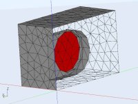
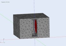
Sub, slotted with 15" driver
A few AKABAK sims based on the physicals and drivers in the Hornresp models. They are close but there are some differences. Hornresp displays power and I display pressure (SPL) in AKABAK. The difference is the radiation surface (directivity) taken into account in AKABAK. Hornresp assumes the drivers are facing the same way, but in a loaded slot the drivers are opposed.
Its a hybrid model. LEM is used for [motors. rear chamber] and BEM is used for all radiation surfaces and outer enclosure.
[edit] The subs are on a floor (IB) so 2Pi space and driven with 2.83Vrms.
Attachments
Last edited:
Are you talking about running the same configuration just difference crossovers?Would it be worth trying a traditional approach. The 18"s in two BR subs up to 100Hz, then the 15" in 1/2 sealed enclosures from 100-400Hz ?
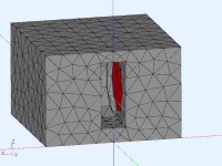
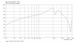
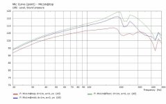
I don't think the dip at slightly above 200hz is from the slot. Heres the response without Damping material in the sealed section.
with Damping material
Last edited:
The dips ~@200Hz are from reflections in the rear chamber. Change the rear chamber length and the dip position will change. Damping will also reduce the dip magnitude. I did not use any damping in the AKABAK models. The slot acts like an unterminated duct to free space and will have its own resonances and reflections but not in the 200Hz area.
When I was looking at the current VLF response (20-40Hz) I was thinking that another tuning 18" in (BR) might help improve it. I tried a few things using your drivers but overall they just pushed the 20Hz even further down (steeper slope). So, the current moderate slope is actually easier to EQ. Then I was thinking about side-side 15" sealed drivers to help narrow horizontal directivity in the 100-400Hz range to better match the horn.
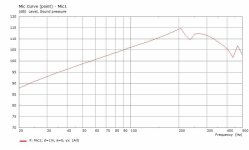
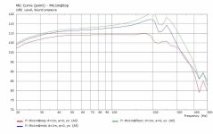
The FR graph below is for the stacked slot arrangement. I applied 6dB boost (20-40Hz), and added an LR4@300Hz. It not flat to 20Hz but it might be sufficient.
When I was looking at the current VLF response (20-40Hz) I was thinking that another tuning 18" in (BR) might help improve it. I tried a few things using your drivers but overall they just pushed the 20Hz even further down (steeper slope). So, the current moderate slope is actually easier to EQ. Then I was thinking about side-side 15" sealed drivers to help narrow horizontal directivity in the 100-400Hz range to better match the horn.
The FR graph below is for the stacked slot arrangement. I applied 6dB boost (20-40Hz), and added an LR4@300Hz. It not flat to 20Hz but it might be sufficient.
Attachments
Thank you @DonVK, I really appreciate the help. I had a whole long reply to explain why I am approaching the system the way I am, versus, a more traditionally crossed 3 way, but its gone... Maybe I can create a quick TLDR.
-I sit really close - ~1m give or take 20inches.
-The CTC is large.
-Tried the horn+15mid+PPSL, Summing was very good, but there is a hint of perception of pressure on the vertical axis even at sub frequency, aka localization
-Concluded that the PPSL could do mid and sub duty with no Ill effect, ~215hz-30hz, high volume, low distortion.
-Removed the mid driver to bring PPSL closer to the Horn, reducing max distance of high to low source from about 40" to 20".
-Concluded that a driver next to a barrier (the floor in this case) provides great FR, sought to keep that as a staple in the design
-Desired to use a Tweeter height at or slightly lower than ear height.
-Raising the tweeter to said height creates an area between the tweeter and floor ridden PPSL to fit a large source, source now we are back to the 3rd aspect of vertical localization... not that summing was bad, but given the close proximity, I perceived the area between the PPSL and Horn as a space where pressure is lower than the axis of the 2 sources in play, thus concluding that I might as well fill it with another source, but this middle source signature truly needs to be identical or close to the PPSL to best dilute the 3rd sound signature.
-Placing another 18" woofer stacked on top of the PPSL, fulfills the ideas of the last thought train but now leads us to a tweeter height several inches taller than desired, and exacerbates Distance from highest/lowest source.
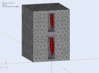
Solution; Shorten 18" PPSL height from 26" to shortest height (20")... addition of 15" PPSL which results in 37" of total height, putting Tweeter Axi at ~46" (goal was 44"-48"). 15" PPSL has more efficiency than the single 15" and now can play without HighPass filter. So the "mid" is back in so many words...

Fs - 43.25 Hz
Qms - 7.22
Qes - 0.178
Qts - 0.174
Mms - 89.65 - grams
Xmax* - ±5.25 mm
BL - 27.43 T.m
Le at 1kHz - 1.01 mH
HP filtered by its own roll off, it maintains the ≤2mm in concert with;

Fs: 29Hz
Qms: 5.9
Qes: .23
Qts: .22
Mms: 165 g
Xmax: 14 mm
Bl: 27.06 T/m
Le: .41 mH
So there will still be a slight difference in FR but with a lower roll off, it will be less perceivable, especially where the frequency is within 1/4lambda.
-I sit really close - ~1m give or take 20inches.
-The CTC is large.
-Tried the horn+15mid+PPSL, Summing was very good, but there is a hint of perception of pressure on the vertical axis even at sub frequency, aka localization
-Concluded that the PPSL could do mid and sub duty with no Ill effect, ~215hz-30hz, high volume, low distortion.
-Removed the mid driver to bring PPSL closer to the Horn, reducing max distance of high to low source from about 40" to 20".
-Concluded that a driver next to a barrier (the floor in this case) provides great FR, sought to keep that as a staple in the design
-Desired to use a Tweeter height at or slightly lower than ear height.
-Raising the tweeter to said height creates an area between the tweeter and floor ridden PPSL to fit a large source, source now we are back to the 3rd aspect of vertical localization... not that summing was bad, but given the close proximity, I perceived the area between the PPSL and Horn as a space where pressure is lower than the axis of the 2 sources in play, thus concluding that I might as well fill it with another source, but this middle source signature truly needs to be identical or close to the PPSL to best dilute the 3rd sound signature.
-Placing another 18" woofer stacked on top of the PPSL, fulfills the ideas of the last thought train but now leads us to a tweeter height several inches taller than desired, and exacerbates Distance from highest/lowest source.
Solution; Shorten 18" PPSL height from 26" to shortest height (20")... addition of 15" PPSL which results in 37" of total height, putting Tweeter Axi at ~46" (goal was 44"-48"). 15" PPSL has more efficiency than the single 15" and now can play without HighPass filter. So the "mid" is back in so many words...
Fs - 43.25 Hz
Qms - 7.22
Qes - 0.178
Qts - 0.174
Mms - 89.65 - grams
Xmax* - ±5.25 mm
BL - 27.43 T.m
Le at 1kHz - 1.01 mH
HP filtered by its own roll off, it maintains the ≤2mm in concert with;
Fs: 29Hz
Qms: 5.9
Qes: .23
Qts: .22
Mms: 165 g
Xmax: 14 mm
Bl: 27.06 T/m
Le: .41 mH
So there will still be a slight difference in FR but with a lower roll off, it will be less perceivable, especially where the frequency is within 1/4lambda.
Thanks @camplo for the context behind the design choices. It would not be very interesting if we all chose the same thing 🙂
I see a few pros and cons with this approach. The pros IMO are : mechanical vibration cancelling, high sensitivity (dB/Vrms more drivers), near continuous slot from floor (boundary coupling), long vertical dimension give better vertical directivity, and no additional mid XO. The cons IMO are : very wide horizontal beamwidth (narrow slot width, room reflections/modes), and possible higher distortion (slot based, freq dependent). It looks like you know what you want. and persistently so 😉
I would be very interested in seeing any measurements of the completed system.
I know things about kerf cutting... because experience has been kicking my butt 🫡
Achieve desired dimension before cutting kerfs...
Use the blade against the side of edge of the wood to judge cutting depth for the Kerf Cuts...
After cutting Kerfs, do not go back through any pervious cuts unless willing to risk losing one of the blades of wood... instead, use a handsaw to fine tune depths, if needed.
Choose a kerf cut depth that leaves 2 ply in tact and try to leave smidge of the 3rd ply. The 1/4th spacing seems to be fine for 18" woofer and 15" woofer mounting holes, my smallest inner diameter being ~14"
Last edited:
You really need good alignment to get the kerfed bend to run anywhere near flush... turns out my kerf spacing was great for the 18" mountings but not so great for 15" mounting holes.... the pictured was a last chance effort before I started designing towards using fiberglass and epoxy for rounded baffle itself. My issue was that there was just a tad too much wiggle room to install the bend while all baffles sitting in the slot. Also can't fit the clamps inside the box. The added resistance helps to allow fine adjustments. So to try and remedy this, I worked outside the box, figuratively and literally, which resulted in what you see... there are some areas where the been is not flush but its is uniform, symmetrical and acceptable... When looking dead on into the box, you cannot tell. I can't say its perfect but for my first time ever on such a project I am still somewhere around a B+ on the construction errors... things that only I will think about when I fall asleep at night, and nothing to do with anything affecting Acoustical Performance, rather, just a desire to do the best. You know, those errors that live beneath the finish, never to be spoken of again lol.

Many times I thought, Why don't I copy the other guys idea and use baffles that have been routed.... To fill the space, I would 6 more 17x15.5 panels, per slot.... 24 if for both boxes... No figure how much more wood I would have needed $$$$ This Kerf bending is working out, and once perfected would be a breeze... to be honest, the least amount of work would be epoxy and a fiberglass fabric though at this point I am just speculating.. I will keep all of this in mind, if I ever had to build another set. 😂

Many times I thought, Why don't I copy the other guys idea and use baffles that have been routed.... To fill the space, I would 6 more 17x15.5 panels, per slot.... 24 if for both boxes... No figure how much more wood I would have needed $$$$ This Kerf bending is working out, and once perfected would be a breeze... to be honest, the least amount of work would be epoxy and a fiberglass fabric though at this point I am just speculating.. I will keep all of this in mind, if I ever had to build another set. 😂
Last edited:
Of course the second install went way smoother. I feel like now, my kerf recipe is fine, but the symmetry of the cuts on the first installation was off causing complex torquing and resistance in between the two baffles. You can see some more of my imperfections in these pictures but glad to say nothing affecting to purpose and functionality of things. It took me two days and hours of play to get the first of this set to work as I desired. This second slot took not even twenty minutes between trial and then gluing... Go Figure.

Symmetry of pieces, is obviously paramount to ease of installation... I'd like to do a layer of Resin Epoxy on the back of the bended piece....
I had the idea of using my sprayer to apply epoxy during the installation of the finish, ie the Fiberglass fabric...I think it will be a good idea to use the sprayer to spray epoxy into the slits to help make sure the bent piece is a permanent thing.
Spraying epoxy seems like a risky procedure unless you have specialized equipment for it. There's not much area to coat so fiberglass cloth (woven) and brushed epoxy would be fine. Otherwise you'd need polyester resin with fiberglass matt (chopped glass) and that's very unpleasant to work with.
I thought I would be able to thin it with iso and spray it from hvlp pressure. I view the sprayer as a much more consistent applicator versus a brush. Its basically an air brush... I got lost when you mentioned poly resin.... Im picturing; applying resin epoxy to the wood surface and to the back of my fabric.. just enough to get it stay permanently... like permanent sticker.
An airbrush or properly called high volume low pressure sprayer (mine has an airbrush sized tip) would allow an even coat to be applied to wood... a brush would work no less, I agree.
I would leave the top side raw if I thought possible, specially if I had a went with a carbon fiber twill weave... the weave

This weave has nylon stitching so it would be wise to put a protective finish on it, plus I'd have a chance to add color if that's what I desire. It seems that a waterbased poly will work on top.
@any advice? @DonVK
An airbrush or properly called high volume low pressure sprayer (mine has an airbrush sized tip) would allow an even coat to be applied to wood... a brush would work no less, I agree.
I would leave the top side raw if I thought possible, specially if I had a went with a carbon fiber twill weave... the weave
This weave has nylon stitching so it would be wise to put a protective finish on it, plus I'd have a chance to add color if that's what I desire. It seems that a waterbased poly will work on top.
@any advice? @DonVK
Epoxy is thick, even low viscosity marine epoxy, and it really can't be thinned very much without ruining the product. I've applied it with a bristle brush (too thick for regular brush) and it settles out to a smooth surface but flows slowly over the working time so you might have to do sections at a time. Maybe, occasionally flip/rotate the box to prevent sagging until set . The brush will help work the epoxy into the kerf slots that might otherwise be shadowed by spraying. I have sprayed lacquer, enamel and water based varnish finishes, but all of these are very thin, use small jet sizes, and settle with few air bubbles.
Epoxy is great for woven fabric because it flows through and does not absorb much epoxy. Fiberglass mat is very different because it has a polyester binder to hold the chopped fibers into a mat. The binder only dissolves with polyester resin but the mat acts like a sponge and holds a lot of resin. Once the binder dissolves, mat can be shaped easily into compound curves because the fibers are free.
My suggestion. Seal the kerf cuts with brushed in epoxy. Any gaps that are still left can be filled with Bondo (polyester filler) and sanded smooth then painted. If you wanted more strength, fiberglass cloth after the bondo fill, or the epoxy will just flow through into the kerf slot, leaving lots of air bubbles under the cloth.
+1, just thin it the recommended amount if your 'air brush' tipped sprayer is near enough the same as my late '60s Binks. Can't get over how cheap its become over the decades.I thought I would be able to thin it with iso and spray it from hvlp pressure. I view the sprayer as a much more consistent applicator versus a brush. Its basically an air brush... applying resin epoxy to the wood surface and to the back of my fabric.. just enough to get it stay permanently... like permanent sticker.
An airbrush or properly called high volume low pressure sprayer (mine has an airbrush sized tip) would allow an even coat to be applied to wood... a brush would work no less, I agree.
The AI suggest that 0.6mm can work... Minimal thinning is suggested for strength. Potentially 3.5% by weight. Either way brushing is always an easy option. @DonVK I wasn't planning on filling the voids in the kerfs... I don't think its needed do you? For example I didn't think it was an issue to cover the voids with the fiberglass fabric. The application of epoxy, to adhere the fabric might be enough to help strengthen the bond of the kerfs to the baffle walls. I will do a small application of epoxy to the rear side of the kerfed wood. I guess that is likely enough to be the nail in the coffin. I'm just feel a little insecure about the wood glue and the tensions of the non perfect fittings is all. Potentially wood glue is enough I am just over engineering.....
- Epoxy Resin: ~70 MPa (0% weaker)
- Oil-Based Polyurethane: ~50-60 MPa (14-29% weaker)
- Water-Based Polyurethane: ~40-50 MPa (29-43% weaker)
- Wood Glue (PVA): ~20-30 MPa (57-71% weaker)
- Spar Varnish: ~15-25 MPa (64-79% weaker)
Last edited:
- Home
- Loudspeakers
- Subwoofers
- High Output Subs that play 20Hz to ≥200Hz