15" woofer. in the Pic/Graph...An 18" woofer built the same way might move the null down to about 498hz, the same build for a smaller sub move the null up in frequency. This approach seems like a good one but I think I'd add damping to the rear half of the slot. HornResp suggest that with optimal Rockwall/Fiberglass in the rear half, the slot will have a much improved FR.


Last edited:
The null is from the top/bottom panels, I believe. It is a 1/2 wavelength cancellation. @GM @weltersys Can one break up modes using baffles... For example a baffle down the axial length of a line, does it shift the resonance/null up an octave, relative to the dimension? So if I ran a baffle splitting the top/bottom.... does that now halve the harmonic there?

Doesn't look like it does, MalVeauX's 51" tall line axially divided into 4 sections 11'x11x3"For example a baffle down the axial length of a line, does it shift the resonance/null up an octave, relative to the dimension?
So if I ran a baffle splitting the top/bottom.... does that now halve the harmonic there?
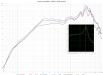
has a similar +10dB peak at 200Hz and ~24dB drop off above as the 15" in post 222:
Yeah thats not true lol. You can prove that to your self by removing the damping material and taking a measurement. In a slot loaded driver, damping material lessens the flaws of the slot. I am not talking about resonances of a panel, I am talking about the resonance of the air column in the slot. I have measurements of my ppsl and they are different depending on the damping situation.
I wasn't talking specifically about only the slot. That's different, its a small cavity. I was saying in general such as the back chamber, it is much larger. I did measure something similar to what...
The Peak comes from axial length reflections. 1/4wL of the depth of the slot... This has not been divided in the design @weltersys . The 51" tall slot according to my reasoning would have a null at 13550/51/2=132.84hz.... The 11" tall slot due to segments ;has a similar +10dB peak at 200Hz and ~24dB drop off above as the 15" in post 222:
13550/11/2= 615.90Hz
So I guess I answered my own question with that one.... An array of baffles to break up the mode created by the vertical length of the slot may be the answer to the issue.
Attachments
Last edited:
You can cut up some pieces of cardboard and hear and measure what an array of baffles does with your slot load 18" to determine if it is an answer to your issue.So I guess I answered my own question with that one.... An array of baffles to break up the mode created by the vertical length of the slot may be the answer to the issue.
There is a rather large conceptual difference between high frequency dispersion vanes placed in the horn throat of a single 1.5" exit compared with putting baffles between opposing 15" cone drivers.
Since the baffles can't be attached to the cones, the sound waves will vertically diffract around them, the effective slot height will be near the same as without them.
Anywhere there is a change in acoustical impedance, a reflection may be.... The sharper the change, the stronger the reflection....
Some manufacturers have used damping materials like Aquaplas or Antivibe to dampen the diaphragm, but loose or pourus damping material between the phase plug and the diaphragm would be a problem unless it could be constrained from contact.@GM or anyone inclined, do they ever place damping material between the phase plug and the diaphragm??? Is damping material touching the diaphragm always, a problem?
Foam damping material in compression chambers often degrades and crumbles over time, which can result in nasty noises when it bounces off the diaphragm.
Does anyone know the source of the Null at ~260hz... The outer edge of the woofers distance correspond with the Null so maybe that is the source.
IF I'm not mistaken, these configurations should render similar FR. IF that's true, then one could use the lower to maintain 100% vibration cancellation and improve the FR. @weltersys is this on track?
Could be out of phase bass reflex port cancellation, which may show up more due to the orientation of the mic if it was a 2meter ground plane measurement.Does anyone know the source of the Null at ~260hz... The outer edge of the woofers distance correspond with the Null so maybe that is the source.
The 2x21" Fulcrum Acoustic US221-2 uses side ports and a "V" load, it's first null appears to be around 475Hz:
Your renditions of "these configurations" don't include where the cabinet walls are located, so it is difficult to determine what your intention is.IF I'm not mistaken, these configurations should render similar FR. IF that's true, then one could use the lower to maintain 100% vibration cancellation and improve the FR. @weltersys is this on track?
If the lower one is a front view of a blue triangular exit in front of a wide slot cavity the height and depth of the drivers, it won't have response similar to "V" loaded drivers as in my L4, Mark100's "V-Twin", or Dave's US221-2.
Art
If the lower one is a front view of a blue triangular exit in front of a wide slot cavity the height and depth of the drivers
They are supposed to be as if looking from above, sorry about that. Top view not Front view, Similar response right? Key word Similar, I just realized this is Not the mirror image I first intended but you probably get the gist. Matter of fact... when you sim an V slot Offset driver in Hornresp, you are simulating this if I'm not mistaken. So with that being said.... I would believe a V shaped phase plug is a viable solution.
response similar to "V" loaded drivers as in my L4, Mark100's "V-Twin", or Dave's US221-2.
I'll see if I cant find raw measurements of V slots
Last edited:
Top View. The Slot would 18" tall by 11" wide, 18" deep with Triangle "phase plug"


Top view, 11" wide V Slot, 17" deep, 18" tall.


I think both of these solutions move the null up. I just wanted to keep the mouth under 11" wide cause
13550/600/2= 11.291 and safety first ....
Top view, 11" wide V Slot, 17" deep, 18" tall.
I think both of these solutions move the null up. I just wanted to keep the mouth under 11" wide cause
13550/600/2= 11.291 and safety first ....
Last edited:
That being said, it's no more a "phase plug" than a "V" load is.So with that being said.... I would believe a V shaped phase plug is a viable solution.
It's a "solution" that requires at minimum two additional pieces of plywood that increases cabinet cost, complexity, and weight while decreasing it's interior volume.
Looks just like the "V" load Fulcrum Acoustic US221-2 response, moved higher due to the smaller driver size.I think both of these solutions move the null up.
Don't you want to be able to tell your friends;It's a "solution" that requires at minimum two additional pieces of plywood that increases cabinet cost, complexity, and weight while decreasing it's interior volume.
I've got 100% Zero net mechanical energy !
Otherwise, I've got some deciding to do. I now have 3 options to get me to 300hz, which will allow all the headroom I'll need if I should ever need it.
I will say out of all of them, I sort of prefer the traditional V slot.
If I go this route with a 5" mouth I think it still works out, but directivity, I wonder.
Last edited:
- Home
- Loudspeakers
- Subwoofers
- High Output Subs that play 20Hz to ≥200Hz