I'm getting the impression that the Kemet DC Link C4AQ capacitors in my CLCRC tube PSU are rolling off the HF. They are 500V or more, 12uF to 40uF. Seems the more I put in the more the rolloff I hear. Typical Electrolytic caps don't seem to do this.
How is this possible? Can anyone explain if and how PSU caps could roll off the HF?
I don't have a scope unfortunately so unable to actually measure what's happening.
How is this possible? Can anyone explain if and how PSU caps could roll off the HF?
I don't have a scope unfortunately so unable to actually measure what's happening.
Try adding a 1uF and a 0.1uF of proper rating voltage. As the capacitance increases, the resonant frequency of the cap goes lower. This mean that over this frequency, the cap abandones its behaviour as cap and acts as an inductor.
Mainly for electrolytic units.
In any case add a 1uF in parallel to overlap its resonant frequency, and the 0.1uF remains capacitive when those actually in the PSU are inductive.
Have in mind that, if those caps are low ESR, the above mentioned is more pronounced than with normal or lytic units.
Mainly for electrolytic units.
In any case add a 1uF in parallel to overlap its resonant frequency, and the 0.1uF remains capacitive when those actually in the PSU are inductive.
Have in mind that, if those caps are low ESR, the above mentioned is more pronounced than with normal or lytic units.
Thanks Osvaldo. These caps are indeed low ESR. So I'm not imagining things.
Do I add the 1uF and 0.1uF to EACH cap in a CLCRC supply or could I add it at the end of the chain?
Do I add the 1uF and 0.1uF to EACH cap in a CLCRC supply or could I add it at the end of the chain?
You can add one set in each of the existent if at hand, but the most important place is the last, where audio path closes around them

Woo guess incoming. After a long stint of neurotic cap swapping my impression is high DA caps such as electrolytics add a layer of low level texture that emulates 'HF air'. The best illustration was comparing mica SSG with Russian non-magnetic Teflon in a coupling position. They both measure extremely well in all important parameters except DA. To my ear the SSG adds a pleasing resolution floor, slightly softening lowest level details. In contrast Teflons could be accused of sounding 'black', which I interpret as transparent to the limits of the source.
Your description suggests circuits designed to minimise high order harmonic distortion. I suspect the reason PIO is so beloved by restorers of older commercial gear designed for the lowest overall THD number with little regard for harmonic order is the high DA lays a big smooth blanket over all sins.
For my present tastes there's no going back. It's the difference between 'sounds great' and sounds great plus being drawn into the musical performance instead of picking up a tablet.
Tell us more.... I know little of DA. How does it affect HF response?Woo guess incoming....
I read polypropylene is around 0.1% DA. Are you saying PIOs are higher?
Looks like I need a capacitor 101 tutorial. Found this on YouTube - I like Dave, the straight-talking Aussie
It's solid state, though. I then need to work out what's happening in tube circuits. Looks like I'm heading for an orgy of bypass caps so what values, what multiples and what capacitor types....?
There's a lot more to power supply caps than I thought.
It's solid state, though. I then need to work out what's happening in tube circuits. Looks like I'm heading for an orgy of bypass caps so what values, what multiples and what capacitor types....?
There's a lot more to power supply caps than I thought.
Hmm. I wonder isn’t what you hear, with increased capacitance, effect of reduced rail harmonics? Any AC load on a CRC or CLC power supply will produce rail modulation at load frequency + harmonics.
With low PSRR single ended tube designs, where supply rails changes are transferred to the amplifier output almost unattenuated, it is possible that it can be perceived as a difference.
I can only offer what was measured at low voltage CRC output, but principle applies. More final capacitance equals less rail modulation.
@tombo56 this is true with pure capacitors, but keep in mind inductance and resistance. If R may be neglected, and L has a definite value, it will resonate with C to create a tank circuit. Over this frequency of resonance, the capacitor no longuer behaves as a cap, but as an inductor. As larger capacitor also has longer foil turns, also its inductance increases and the resonant frequency decreases too. Thus, larger capacitor not needly means better performance in high frequencies.
If series resistance is low, the peak of resonance is higher and thinner ( big "Q" ) thus problem is still bigger.
If series resistance is low, the peak of resonance is higher and thinner ( big "Q" ) thus problem is still bigger.
There is no doubt about resonant impedance peaks and that they are big.
Mentioned Kemet C4AQ (500 - 650 V, 12 - 40 uF) have ESR in the 3 - 7 mΩ range and ESL in the 8 - 24 nH range. That results with above 300 kHz resonant frequency, that should have no effect to audio range.
Rail modulation example, that I’ve attached, is measurement taken on the real circuit and conditions.
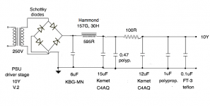
I've made a "test" PSU chassis with plenty of room to try out options. My first experiment sounds better overall, but I think there's a little hum - probably because of the small value caps. Treble is better and so is the midrange. This is just for the driver tube, a 10Y in filament bias, which I'm powering separately for now.
Where to go from here in terms of changes and improvements?

Where to go from here in terms of changes and improvements?

I added a 68uF electrolytic but the sound went quite dead and I lost some of the high frequencies. As shown. This was not an improvement, although it looked like the right thing to do in theory. I really didn't like it. Back to the drawing board.
Suggestions?

Suggestions?
Andy,
If you use SS full bridge (Graetz), the first cap ripple current will be enormous (even few hundred mA).
Are you sure that this russian block capacitor made for this requirement?
If you use SS full bridge (Graetz), the first cap ripple current will be enormous (even few hundred mA).
Are you sure that this russian block capacitor made for this requirement?
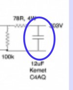
Good question Bela. I don't know the answer. The cap is Russian KBG-MN 6uF, 400V. It's very big if that matters. 110 x 82 x 32mm. It's a film cap - alleged copper PIO. What bad effects might I expect?
Next version eliminates the 68uF electrolytic and substitutes a 15uF Kemet C4AQ DC Link cap with a 0.47uF MKP bypass.
This is a better sound overall - tonality is distinctly better than the electrolytic. It's not as lively as the previous version with just the 12uF C4AQ + 1uF bypass after the choke. That remains the best so far. This one is a bit smoother and a bit more dead sounding, but tone is still good.
I don't have PSUD because I have a Mac, unfortunately.
At a future point I should try choke input but that would require a higher voltage transformer.
Attachments
Last edited:
Fourth version, V.3 has 12uF and 15uF C4AQ in parallel, with 1uF and 0.1uF bypasses. This is a good sound. Good tone and lively sounding with decent treble. So looks like I can go up a bit in value from 12uF in the C4AQ caps. I have some 20uF C4AQ coming in the post. I'll experiment with the value. This is getting nearer to the sound I want.

IMO you are going wrong way. The usual way of designing the PSU for the best performance achievable, and change the amp behavior in the direct audio path, it is the logic job. It is obvious that you can do what you want, but this way you are introducing an incontrollable parameter: line impedance, that is reflected into the PSU performance. As a check, maintaining the PSU as is, and add a 20mts extension in the outlet to the amp power input and listen if you found differences, honestly.
Thanks Osvaldo, I value your contributions. I deliberately wanted to listen to several alternatives, and yes I can hear the differences. I have a very rigorous listening procedure - carefully chosen test tracks for acoustic instruments and voices, and I play the same 4-5 tracks every time at the same volume. I'm a conservatoire trained musician and I'm very familiar with the tone of acoustic instruments since I've played alongside a variety of them in orchestras, theatres, clubs etc. for many, many years. That's how I do it.
But of course I want to check all this against the theory. I wish I could measure all this better, that would be a help.
What do you mean about line impedance? The PSU is connected to the 10Y stage via a 1 metre long cable. Is this what you are referring to? I should shorten this optimally.
But of course I want to check all this against the theory. I wish I could measure all this better, that would be a help.
What do you mean about line impedance? The PSU is connected to the 10Y stage via a 1 metre long cable. Is this what you are referring to? I should shorten this optimally.
- Home
- Amplifiers
- Power Supplies
- High frequency roll-off in PSU caps?