I tested directly on the fets. Now i tested again on pin 1. One side i have a signal on pin 1, other side nothing. Without solder bridge i have 150V DC on the conductors.
Wich collector? Pin 1 on 21844s? On pin 1 i have a drive signal, but only on one of the 21844s.
Did you mean i should check Q2 and Q7 Collector for drive signal?
Did you mean i should check Q2 and Q7 Collector for drive signal?
The signal passes through two 10k resistors to pin 1 of the driver ICs. Are the 10k resistors good?
Do you have good connections between all of those components?
Did you have signal on the dead pin 1 before replacing the IC?
Do you have good connections between all of those components?
Did you have signal on the dead pin 1 before replacing the IC?
I havent checked the signal without ic... Its very difficult to find the right resistors. If i measure from the collector to pin 1 i got on both parts the same value.
Has the signal on pin 1 of the IC with no signal changed since you replaced the IC?
Is the DC voltage on pin 1 0v, referenced to the negative rail?
Is the DC voltage on pin 1 0v, referenced to the negative rail?
No, the signal has not changed. Iam not sure where to find the right place for my probe on negative, but if i connect one probe on pin 1 and the other on the rail bar i have 150v, on first pin of the fet 80V.
With the new IC, if you short both ICs pin 2-3, do you still have DC on the output inductors?
Do you have a 10k through-hole type resistor?
Do you have a 10k through-hole type resistor?
if i short them, there is no more dc on the inductors. Yes i have a 10k resistor.
Found the resistors. Pin 1 is going to a 10k, from there to a 3,4k and from this to q2 base.
If i measure directly from pin 1 to Q2 Base i got 10k. Other side the same.
Found the resistors. Pin 1 is going to a 10k, from there to a 3,4k and from this to q2 base.
If i measure directly from pin 1 to Q2 Base i got 10k. Other side the same.
Last edited:
Leave the 2-3 bridges.
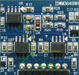
Solder the 10k resistor to the points indicated by the arrows below. One end to any green. The other end to any yellow.
Driving a signal into the amp, do you see the same drive frequency square wave at pin 1 of the two 21844s?
Solder the 10k resistor to the points indicated by the arrows below. One end to any green. The other end to any yellow.
Driving a signal into the amp, do you see the same drive frequency square wave at pin 1 of the two 21844s?
Attachments

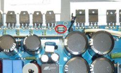
Ground the scope to the wire-type shunt resistors used for current sensing. Set the scope to manual. 2ms//div and 5v/div. Set to DC coupling. Center the trace on the reference line.
- Status
- Not open for further replies.
- Home
- General Interest
- Car Audio
- Hifonics BXI-6000D