Thats a lot of info.. yes i have a separate powersupply that i could use instead.
I'll wil renew the voltage regulators to. But the last time i meassured both regulators. They are 15v 7815 and negatieve 7915. Both power output where in working order. I have to look for the 12v regulators. 5v was ok too on the test.. i will test the rest if i have my components.. will reply on this on a few days. This is really good info to keep me sharp!
I'll wil renew the voltage regulators to. But the last time i meassured both regulators. They are 15v 7815 and negatieve 7915. Both power output where in working order. I have to look for the 12v regulators. 5v was ok too on the test.. i will test the rest if i have my components.. will reply on this on a few days. This is really good info to keep me sharp!
You where right again, TVS diode P6KE600 had a strange value. Other side looks okay. So ordered these too. There's a lot going on, in this amp.
Hope it will function afterwards. The capaciter 1u connected to the TVS diode was ok. Come back if i know more!
Hope it will function afterwards. The capaciter 1u connected to the TVS diode was ok. Come back if i know more!
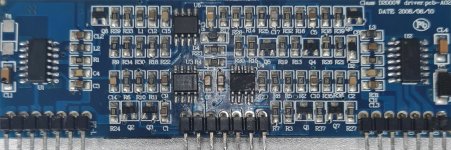
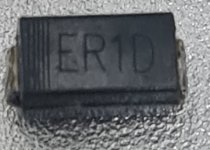
Started doing some rework on driver pcb, after some strange values meassuring on pins of pcb. Replaced 21488's. Found the ER1D diode that had some strange values. Desoldered it, and tested it without anything else connected to it. In forward value ok. But in reverse 1020mv on diode test. Also dead diode D1. The short must have damged a lot of parts on this side of the amp. Rest of transistors and diodes on pwm board ok. Now i have to wait for the ER1D diodes. Tvs diodes didn't arrive yet. So wait a few days more, to do some more rework on the amp..
Attachments
Another problem..ordered 15pcs FQA38N30, today i got delivered 15Pcs FDA38N30? Equivelent? Looked both datasheets, there are some differences do.
But online , there all talking about the best subtitute for this part. Is it true, or do i get other problems with this..?
But online , there all talking about the best subtitute for this part. Is it true, or do i get other problems with this..?
Attachments
I think they should be OK but if someone knows definitively that they will not work, please say so.
Test all drive signals before installing the outputs to make sure that, if there is a problem, you know that the problem was not from the drive circuit.
How many of the original FETs that are still good, do you have left?
Test all drive signals before installing the outputs to make sure that, if there is a problem, you know that the problem was not from the drive circuit.
How many of the original FETs that are still good, do you have left?
The reason I ask is that you can use them (after checking them very carefully) to confirm thst all is well with the drive. Then you can use the outputs. If there isn't a problem with the new ones, either, test thoroughly after reassembling the amp and there are no problems then, these are likely perfectly good substitutes.
You can test one side at a time.
You can test one side at a time.
Ok, will check the difference, if there is any.. The worst thing, is waiting for the parts to arrive. 🙂
By the way, last time you asked me if i had a sperate powersupply tot test. Wat kind of supply do you use to test. Voltage /current instead of onboard supply.
And have to diconnect old supply to connect substitute right?
By the way, last time you asked me if i had a sperate powersupply tot test. Wat kind of supply do you use to test. Voltage /current instead of onboard supply.
And have to diconnect old supply to connect substitute right?
When I believe or know that there is a problem destroying FETs and I can't determine why, I make my own supply (I didn't have a split supply). Using a low-voltage supply isn't likely necessary.
This thread explains what I did for problem amps.
https://www.diyaudio.com/community/threads/4000-1.319174/page-4#post-5493113
This thread explains what I did for problem amps.
https://www.diyaudio.com/community/threads/4000-1.319174/page-4#post-5493113

Initially, test with the old (good) FETs to confirm that all is good with the drive circuit. When you're 100% sure that the drive is OK, then you can install the new FETs.
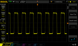
yesterday i installed the driver board, and installed the fets in one channel. Went well, installed the new ones in channel one. I'm little curious about the gate signal.. Is this normal?
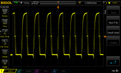
After it stayed on, i inserted a 50Hz signal with signalgenerator. Works well.. Without any stange signals. see output 50HZ speaker output.
The only thing i have , is that when its switched on, there's a smal amount of noise on output. I will see if i can attach and soundfile, so that you can hear it. Its not not loud, but i can hear it. Like tuning in on shortwave radio.. When bendeing the powersupply card, it goes away, and comes back again..
Attachments


If the noise is like the following file, it's normal for amps with un-synchronized oscillators.
https://www.bcae1.com/temp/cooleditmixedoscillator01.wav
Manipulating the driver board is likely changing the frequency slightly which will affect the noise.
The ch2 gate has slightly more slope on the rising side than I'd expect, especially when having the other channel for comparison. Is everything for both channels identical?
Yes! it's the same noise, only not so loud, but its allmost identical! So no problems with powersupply oscillator..
I think that de difference is that, channel one has the new type Fets FDA38N30, en channel two has the FQA38N30 that where standaard in the Amp.
I did that to compare. But if that ai'nt gonna be a problem, i leave them inside.
Output signal is really perfect. no signs of distorsion.
I think that de difference is that, channel one has the new type Fets FDA38N30, en channel two has the FQA38N30 that where standaard in the Amp.
I did that to compare. But if that ai'nt gonna be a problem, i leave them inside.
Output signal is really perfect. no signs of distorsion.
I also checked it with Fets out of the board.. Square wave is super sharp. so think signal alters with fets inside the board..
Any ideas of bench test this, for high output. Can this be done with a kind of dummyload.. or do i need special equipment for that...
Any ideas of bench test this, for high output. Can this be done with a kind of dummyload.. or do i need special equipment for that...
The capacitance of the gate of the FETs and the gate resistance alter the wave shape.
You can test with a dummy load. Do you have a 12v power supply that can power this amp at/near full power?
What ohm is your dummy load?
You can test with a dummy load. Do you have a 12v power supply that can power this amp at/near full power?
What ohm is your dummy load?
yes have a dummyload, but not for this kind of aplications.. it's a 50 Ohm dummieload.. so won't help.. But can arrange one with wirewound resisitor. What type of load i should get? Have a 200 Amps supply 13.8v
- Home
- General Interest
- Car Audio
- Hifonics BXI 6000D wire location