Measure the DC voltage across the collector and emitter of Q51 for the same period of time.
Are the 21844s still disabled?
Are the 21844s still disabled?
I've got no Q52
Q51 seems fine, D51 is in this circuit a 3V6 Z-Diode. I just replaced the Z-Diode.
It is weird? that the Z-Diode isn't stabilizing at the 3,6V.
The equivalent of Q52 is maybe on the output Board or the Q1 at the PS Side of the Main Board.
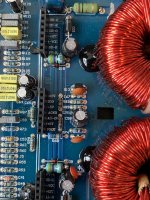
I noticed that both output Relais are getting hot. The output filter stays cool.
Q51 seems fine, D51 is in this circuit a 3V6 Z-Diode. I just replaced the Z-Diode.
It is weird? that the Z-Diode isn't stabilizing at the 3,6V.
The equivalent of Q52 is maybe on the output Board or the Q1 at the PS Side of the Main Board.
I noticed that both output Relais are getting hot. The output filter stays cool.
Find the transistor that has one terminal connected to pins 6 and 16 of the driver board and another terminal connected to the negative rail.
That´s Q51 (Q13 on my board), but it is connected to Pin 6 and 16 over 2 Diodes which is then connected to the Muting Transistors of the Output Driver board. Emitter is connected to negative rail.
What's the part number on that transistor?
Q52 on that diagram is connected through the diode(s) and also connected to the negative rail, on that diagram.
I was using a different diagram (many similar) and it didn't have the diodes.
Q52 on that diagram is connected through the diode(s) and also connected to the negative rail, on that diagram.
I was using a different diagram (many similar) and it didn't have the diodes.
With just B+ and ground connected, what's the DC voltage across the zener diode?
What's the DC voltage across the relay coils when the amp is powered up?
What's the DC voltage across the relay coils when the amp is powered up?
Posts 52 and 54 seem to be in conflict.
Mark the diagram that was posted with the circuit board designations and part numbers for the parts on your board and post it.
Mark the diagram that was posted with the circuit board designations and part numbers for the parts on your board and post it.
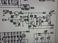

What is the DC voltage on each side of R55 on the diagram, B+ and ground connected, no remote, black meter probe on ground terminal of the amp?
I don't know how you marked the diagram but you can do this in the PDF viewer and leave the file in digital format.
I don't know how you marked the diagram but you can do this in the PDF viewer and leave the file in digital format.
- Home
- General Interest
- Car Audio
- Hifonics BXi 6000D - Drive cuts out