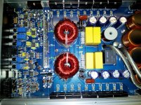
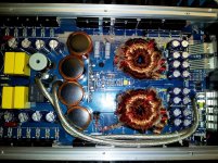
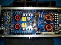
I was running this amp at 0.5 ohms for 3 months and then the amp would start going into Protect at high volumes. It then started going into protect at medium-high levels so I re-wired my subs to be at a 2 ohm load but amp still went into protect. After getting into protect about 10 times, it finally gave out and stayed in protect. During troubleshooting I reconnected the amp and heard a pop and smelled something but no visible smoke and now the amp is no longer in protect but has no output. Attached is a few pictures of the amp. I have not taken any measurements but in the center of the board between the 8gauge speaker wires shows a blown 10uF 250V capacitor. I have already ordered a replacement cap with same specifications and I was going to give that a try first. Can anyone point me in the right direction of other problems that can be going on while I wait for the cap to be shipped?
PS..I never took apart this board so if anyone can instruct me on how to take off the retaining clips from the heat sink sides that'd be great.
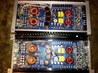
Also the BRZ2400.1D and BXI2600 series uses the exact same board and components. Last picture is with both amps side by side.
PS..I never took apart this board so if anyone can instruct me on how to take off the retaining clips from the heat sink sides that'd be great.
Also the BRZ2400.1D and BXI2600 series uses the exact same board and components. Last picture is with both amps side by side.
Attachments
For the clips, click HERE.
The capacitor may cause it to go into protect but there are several SMD transistors (Q7, 11, 19 and 22) on the driver board that commonly fail and can make the amp go into protect.
Did you order a non-polarized capacitor?
I am not too sure if I got a polarized or non one but this is the one I orderedHERE. I just matched specs for capacitance, operating temp, and voltage...Did I get wrong one? Also by driver board, are you referring to the little circuit board that plugs into the main big board? Sorry for being noob...
That's a polarized capacitor. If it's connected across the speaker output, as I assume that it is, it won't work. The mouser part 667-ECQ-E2106JF will work but it's a different type of capacitor so it won't mount the same way as the original.
Yes. The driver board is likely marked DWM1216.
Yes. The driver board is likely marked DWM1216.
I'm going to look into the amp again and see if I see markings for polarity in the cap. Still trying to brush up on my EE but the cap I got is polarized because the legs determine the polarity right? And the one you referred me to is AC so polarity shifts.
Also, do I just test the SMD transistors same way as regular legged transistors?
Also, do I just test the SMD transistors same way as regular legged transistors?
Yo can't go by the markings on the board. Some board layouts use polarized markings regardless of the capacitor.
The capacitor is rated for DC voltage, not AC voltage. Many polarized capacitors don't work well with DC.
The capacitor is rated for DC voltage, not AC voltage. Many polarized capacitors don't work well with DC.
Okay I see. Thanks for the clarification! I will report my findings once I start taking taking measurements.
So I am going to get the caps you recommended since that's the only place I can find them in stock and shipping to me is $7 so I was thinking about getting a few other parts just so that I don't waste my money on shipping. I was thinking about what I should also get that would usually fail. Here are the following transistors along the heat sink I have on my board:
Qty | Model
12 IRFPO64N
4 MU32U
10 FQP12P20
10 FQP19N20
1 KA7915
1 KA7815
I did try to get some resistance values between legs on the transistors and some seem to be shorted but I am not sure if I did the procedure correctly and that I did not remove any of the transistors off the board to test individually.
Last thing was that on the driver board, the chip doesn't pop out right? Its soldiered in the board? I don't want to tug the crap out of it if it is soldiered.
The regulators and rectifiers rarely fail. The output and power supply transistors are more likely to fail if there is a mistake when hooking it up.
All components on the board are soldered in place.
All components on the board are soldered in place.
I quickly checked the transistors along the side of the board. I did not pull any off, I just measured the resistance between the outer legs and this is what I got:
Left side of board:
5 FQP12P20 = 19.88 kohm
5 FQP19N20 = 19.80 kohm
6 IRFPO64N = 0.8 ohm
Right Side of board:
5 FQP12P20 = 12.5 ohm
5 FQP19N20 = 32.1 ohm
6 IRFPO64N = 0.8 ohm
Is this method okay to use? I know I really should pull the transistors off the board but I am on a crunch for time. The IRFP064N's catches my eye along with the right side of the board. I have not checked the driver board yet because I don't want to start unsoldiering. Let me know if I should perform other procedures.
Last edited:
The output transistors on the right side appear to have failed. You need to replace those and all of the power supply FETs.
When checking semiconductors, you should not read anything near 0 ohms between any of the legs, no matter the orientation of the probes. Generally, the only exception is the rectifiers. The outer legs of the rectifiers in most amps will appear to be shorted because they are connected across the secondary windings of the power transformer.
When checking semiconductors, you should not read anything near 0 ohms between any of the legs, no matter the orientation of the probes. Generally, the only exception is the rectifiers. The outer legs of the rectifiers in most amps will appear to be shorted because they are connected across the secondary windings of the power transformer.
For thermal paste I know you recommend Dow Corning 340 but the tubes I find (5oz) is more than I need. Is there an alternative that will work just as good for much cheaper price?
Radio shack has small tubes of heatsink compound. Sometimes it's dried out (or just too thick to be displaced properly) but if you get a good tube, it's usable.
There are also smaller tubes of compound available from Digikey. Search for Wakefield. The 345-1006 or 345-1007 may be what you're looking for.
There are also smaller tubes of compound available from Digikey. Search for Wakefield. The 345-1006 or 345-1007 may be what you're looking for.
I went and pulled out some of the output fets and they checked out to be good (diode check) but with the fets not in the board I went and checked the outer pin holes resistance and it read same value even if the fets were still soldered in. I then checked the resistors right next to each fet and one resistor value matched the color band but the other resistor was way off. Here is what I got:
Right Side
Resistor Yellow, Purple, Brown, Gold = 8.5 ohm Resitors along Power Fets
Should be = 47ohm
Brown Black Yellow Gold = 19.88kohm *Resistors along output fets*
Should be = 100kohm
Brown Black Black Gold = 10 ohms*Resistors along output fets*
Left side
Yellow, Purple, Brown, Gold = 8.5 ohm *Resitors along Power Fets
Should be = 47ohm
Brown Black Yellow Gold = 5-33 ohms * Resistors along output fets*
Should be =100kohm
Brown Black Black Gold = 10 ohms * *Resistors along output fets*
The thing that bugs me is that each resistor has the same wrong value. For example, the brown black yellow gold should be 100kohm but all 5 of them on one side read 19.88kohm and I was taking the readings directly between the resistor. Is that normal? Also can my amp be going into protect if the resistance values aren't true?
For the 100k resistors, they may essentially be in parallel which would make five 100k resistors read 20k.
If you're concerned about the others, desolder one leg and re-check them.
If you're concerned about the others, desolder one leg and re-check them.
I realized that I was measuring parallel resistance and removed all fets and got the right value once the bad fets were out. I have replaced the rows that had bad fets and replaced the blown cap.
The amp works but there is now a noticeable high pitch noise coming out of the speaker. The noise stays the same sound level ands the sound regardless if the signal RCAs are in or not. Basically if I turn on the amp and just connect the speaker wire only, it makes the high pitch sound.
What can it be? I'm thinking it might be because the different capacitor I put in but not really sure. Anyway I can go about trouble shooting? Can I clip off a lead on the cap and see if it still happens?
Does it sound like someone tuning a shortwave radio?
How loud is the sound?
What sort of speaker are you using for testing?
How loud is the sound?
What sort of speaker are you using for testing?
I am using a 8inch Midbass driver. The sound being produced is not really high pitched but it is in the region of 1500 Hz to 3000 Hz comparing it to my freq generator on my computer. The sound is not too loud, it almost the similar tone you'd hear when you have a bad ground causing engine noise but this one doesn't change tone or volume, its the same tone and volume regardless if you turn the gains, crossovers, boost, or signal input volume. The sound is faint but you can defiantly hear it if your driving with no music and windows up.
- Status
- Not open for further replies.
- Home
- General Interest
- Car Audio
- Hifonics BRZ2400.1D No Output...Used to be in Protect